| Version 9 (modified by , 13 years ago) ( diff ) |
|---|
How to calculate "real" parameters from affine transformation
Introduction
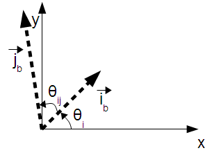
This page discusses how to compute physically significant parameters from an arbitrary linear transformation. The reverse process, calculating the affine parameters from the physically significant parameters, is articulated on another wiki page. The model used to describe how the raster maps onto real world coordinates is illustrated in the following figure:

This model contains all of the parameters except for translation. Translation may be added in after the coordinates have been scaled, rotated and sheared. The above illustration contains the physically significant parameters which will be calculated by this method. These are: θi, θij, and the pixel size along the ib and jb basis vectors.
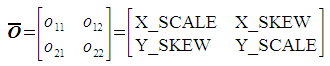
The inputs to this method are the four non-translation (non-offset) parameters of a linear transform. These are shown below:
![]()
Although these parameters have "common names" within the GIS community, the names are both lengthy and misleading. Within the context of this page, the coefficients o11, o12, o21, and o22 will be used.
This page is divided into sections. Each section describes the computation of one physically significant parameter.
Pixel size in the i direction
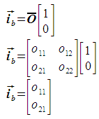
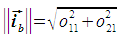
To calculate the pixel size in the i direction, the i unit vector is projected using the given transform. This gives the basis vector ib, the magnitude of which is the pixel size. The basis vector is expressed as follows:

The pixel size is then calculated as follows:

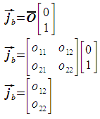
Pixel size in the j direction
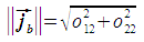
The pixel size in the j direction is computed in a manner similar to the pixel size in the i direction. The only difference is that the j unit vector is used in place of the i unit vector. This gives the basis vector jb, the magnitude of which is the pixel size. The basis vector is expressed as follows:

The pixel size is then calculated as follows:

Rotation
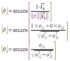
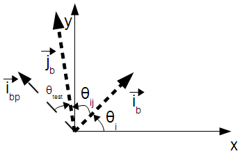
The grid is rotated by the angle θi. This is the angle between the x axis of the reference frame and the ib basis vector. The angle θi is considered positive in the clockwise direction, for consistency with compass headings. The calculation of θi is a two-step process: first the magnitude is calculated, then the sign is determined. Both steps involve using the dot product to determine the angle between θi and one of the axes of the target coordinate system (either the x axis or the y axis. The equations in this section refer to the angles and vectors defined in the following figure:

The first step is to calculate the magnitude of the angle between ib and the x axis. This is the magnitude of θi.

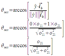
The angle θi is defined as the angle from the x axis to ib. It is positive in the clockwise direction. In the situation described in the above figure, this means that θi is negative if ib is above the x axis, and positive if below. We determine whether ib is above or below the x axis by finding the angle between ib and the y axis. If ib and the y axis are separated by less than 90 degrees, ib is above the x axis, otherwise it is below.

So, if θtest is less than 90, θi = - abs(θi). Otherwise, θi = abs(θi).
Basis vector separation angle
In this section, the method to calculate θij is presented. This is similar to the method for the calculation of θi, but it is accomplished with respect to the rotated reference frame of ib and ibp instead of the x and y axes. The figure which represents this setup is as follows:

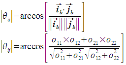
The first step is to calculate the magnitude of θij, the angle between ib and jb.

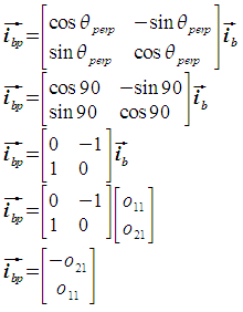
Next, we need to determine the sign of θij in a manner similar to how the sign for θi was determined. The angle θij always represents the angle from ib to jb, and is positive counterclockwise for consistency with a right-handed coordinate system. To do this, we first need to calculate ibp, which is perpendicular to ib and forms a right-hand coordinate system with ib. Observe that ibp is ib after a 90 degree counterclockwise rotation.

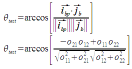
Now we can determine the size of the angle between jb and ibp. In this situation, any angle less than 90 degrees means that jb is on the same side of ib as ibp. An angle more than 90 degrees means it lies on the opposite side.

So, if θtest is more than 90 degrees, θij = - abs(θij). Otherwise, θij = abs(θij).
If θij has any value other than +-90 degrees, the basis vectors are not orthogonal and the transformed pixels are diamond shaped. Probably the most common value for θij is -90 degrees, which indicates that the transform "flips" the j axis.
Summary
The method presented here performs calculations in the coordinate system used by the geocoordinates. All of the parameters calculated by this method are tied to the same SRID referenced by the transform O. It is assumed that the x and y axes of the geospatial coordinate system are orthogonal.
See also
- Wikipedia article on the dot product.
- Wikipedia article on coordinate systems.
- Wikipedia article on the world file.
- How to calculate a transform based on physically significant parameters.
Attachments (13)
- geotransform.png (2.1 KB ) - added by 13 years ago.
- model.png (5.5 KB ) - added by 13 years ago.
- basisvector_i.png (2.0 KB ) - added by 13 years ago.
- basisvectormag_i.png (974 bytes ) - added by 13 years ago.
- basisvector_j.png (2.1 KB ) - added by 13 years ago.
- basisvectormag_j.png (1019 bytes ) - added by 13 years ago.
- calc_theta_i.png (6.2 KB ) - added by 13 years ago.
- thetamag_i.png (4.3 KB ) - added by 13 years ago.
- thetatest_i.png (4.6 KB ) - added by 13 years ago.
- calc_theta_ij.png (7.1 KB ) - added by 13 years ago.
- basisvector_ip.png (5.0 KB ) - added by 13 years ago.
- thetamag_ij.png (3.4 KB ) - added by 13 years ago.
- thetatest_ij.png (3.5 KB ) - added by 13 years ago.
Download all attachments as: .zip