WCS Basics and GDAL
WCS is designed for serving potentially multidimensional (2D surface of the earth, depth, elevation, time) complex data (multiple measurements from a single point or area). The server needs to describe both the coordinate system and the internal organization of the data, and also its extent and magnitude respectively. The coordinate system is described as axis names and reference systems. The extent of the data in the coordinate system is given as an envelope. The internal organization (relationship between axes of data and coordinate system axes) is described with a sequence rule, which is by default linear and increasing in the order of the coordinate axes but the order and whether data is arranged first to last or last to first along the axis can be changed.
The data is further tied to the coordinate system with starting point (indexes) of data, location of the origin of the data in the coordinate system, and with offset vectors. The starting point of data is by default the first data point. The offset vectors give coefficients for converting data point locations into coordinates. The offset vectors are in the order defined by the sequence rule. The magnitude of the data is given as an envelope, which gives the number of data points along each data axis.
The situation is much complicated by the fact that coordinate systems defined for the surface of the earth can be set up in many ways. It is common to have the first axis to point east but it is possible to have it pointing north. Also the data can organized internally for computer in many ways. GDAL traditionally calls the organization sequences of pixels that form lines, which form sequences of lines. In GDAL the first data point is assumed to be at the location of (0,0) in the pixel,line coordinates, and that the pixel,line coordinates increase linearly. GDAL also traditionally associates pixels with X axis of the coordinate system and lines with Y axis of the coordinate system. GDAL uses the concept of a GeoTransform to tie the data points to the coordinate system. The GDAL GeoTransform defines the minimum or maximum of the X and Y coordinates associated with the first data point (there it assumes that the data point (value) represents a rectangular area; whether the values are minimum or maximum depends on the signs of the first and third coefficient), and the coefficients (above offset vectors) for computing the X,Y coordinates for any data point (again, the min/max X,Y coordinates associated with it).
GDAL usually expects the coordinate system to be such that X increases eastward and Y increases northward. (I'm not sure about this. "usually" is also not a good word in computing. I think Even mentioned something like this in an email some time ago. Probably this applies to situations where coordinate system transformations need to be made). GDAL has functions to detect the cases where coordinate systems differ from the GDAL concept of first axis east, second axis north. When such coordinate systems are detected in WCS, the order of all things related to the two axes is swapped. This means axis labels, and coordinate values among other things. The swapping happens in all communication, that is, when parsing a response from a server and when constructing a request.
to write: what happens if the internal organization of data that is served over WCS is not according to what GDAL assumes (data axis order, sequence)
to write: WCS servers may allow asking data in CRS that is not the CRS the coverage is described. If GDAL sets the CRS of the dataset into that CRS, it needs to set its GeoTransform and raster size accordingly. That requires projection transformation.
to consider: What if, for some reason, somebody makes a WCS server that supports both GeoTIFF and Windows BMP, or some other format that is having the origin at the lower left corner instead of top left corner. Theoretically there should be different DescribeCoverage responses for these cases with different grid origins and offset vectors. The OSGeo recommendation might be to avoid such output formats.
GDAL WCS Driver and Interoperability
This table describes the interoperability of the GDAL WCS driver (new version, currently in development) with various WCS servers. (Results are tentative. Also, ArcGIS WCS server serving data with inverted axis CRS is not yet tested, and MapServer and Rasdaman serving data in normal CRS is not yet tested.)
| 1.0 | 1.1 | 2.0 | |
|---|---|---|---|
| ArcGIS | Result with normal CRS: OK | Result with normal CRS: GridOffsets must dx,dy, i.e., without 0,0 | Result with normal CRS: Only scaleFactor seems to be supported. Getting the expected size seems to be a bit of a guessing game. |
| GeoServer | Result with normal CRS: OK, with inverted axis CRS: OK | The bounding box should contain the cell areas. If GridOffsets is set to "0,dx,dy,0" for inverted CRS, the result is very close to expected but slightly different size (in a test 59x38 instead of 60x38). Also for inverted CRS the GridCRS coordinates should not be inverted. | Inverted CRS: subset axes need to be inverted, grid axis order should not be swapped although sequence order says so |
| MapServer | Results with inverted axis CRS: OK | Results with inverted axis CRS: GridOffsets must be abs(dx),abs(dy), i.e., without 0,0 and positive. GridCRS coordinates should not be inverted. | Results with inverted axis CRS: Grid axis labels must not be swapped; Grid otherwise ok since no coverageFunction |
| Rasdaman | Not supported | Not supported | Results with inverted axis CRS: OK |
WCS Best Practices for Interoperability
This page is created for gathering best practices about how to use WCS so that it 1) is standard compliant 2) helps with achieving interoperability between different implementations.
Related mailing list threads:
https://lists.osgeo.org/pipermail/gdal-dev/2017-April/046366.html
https://lists.osgeo.org/pipermail/gdal-dev/2017-November/047650.html
Test data
Note to authors
Add DescribeCoverage documents from different servers as annexes. Name should reveal the server and WCS version.
Sample image A from the WCS KISS dataset (GeoTIFF as an annex)

Sample image B from the WCS KISS dataset (GeoTIFF as an annex)

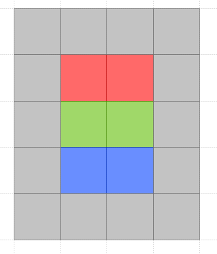
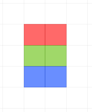
Image A is an exact SUBSET of image B
Images are of type "pixel is area". The pixel centers are also shown in this image
![]()
Extents of the test images
1) In first case the raster images are somewhere in Chine where the longitude is greater than 90. Polygons which contain completely all the pixels are in the PostGIS EWKT format:
Image A: SRID:4326;POLYGON (( 115 30, 115 33, 117 33, 117 30, 115 30 ))
Image B: SRID:4326;POLYGON (( 114 29, 114 34, 118 34, 118 29, 114 29 ))
Image A has width=2 and height=3 and it can be constructed from an array: [Red,Red,Green,Green,Blue,Blue]
Image B has width=4 and height=5 and can be constructed from an array: [Grey,Grey,Grey,Grey,Grey,Red,Red,Grey,Grey,Green,Green,Grey,Grey,Blue,Blue,Grey,Grey,Grey,Grey,Grey]
A.tfw
1
0
0
-1
115.5
32.5
B.tfw
1
0
0
-1
114.5
33.5
Gdalinfo reports
gdalinfo WCS_KISS_A.tif
Driver: GTiff/GeoTIFF
Files: WCS_KISS_A.tif
Size is 2, 3
Coordinate System is:
GEOGCS["WGS 84",
    DATUM["WGS_1984",
        SPHEROID["WGS 84",6378137,298.257223563,
            AUTHORITY["EPSG","7030"]],
        AUTHORITY["EPSG","6326"]],
    PRIMEM["Greenwich",0],
    UNIT["degree",0.0174532925199433],
    AUTHORITY["EPSG","4326"]]
Origin = (115.000000000000000,33.000000000000000)
Pixel Size = (1.000000000000000,-1.000000000000000)
Metadata:
  AREA_OR_POINT=Area
Image Structure Metadata:
  INTERLEAVE=PIXEL
Corner Coordinates:
Upper Left  ( 115.0000000,  33.0000000) (115d 0' 0.00"E, 33d 0' 0.00"N)
Lower Left  ( 115.0000000,  30.0000000) (115d 0' 0.00"E, 30d 0' 0.00"N)
Upper Right ( 117.0000000,  33.0000000) (117d 0' 0.00"E, 33d 0' 0.00"N)
Lower Right ( 117.0000000,  30.0000000) (117d 0' 0.00"E, 30d 0' 0.00"N)
Center      ( 116.0000000,  31.5000000) (116d 0' 0.00"E, 31d30' 0.00"N)
Band 1 Block=2x3 Type=Byte, ColorInterp=Red
Band 2 Block=2x3 Type=Byte, ColorInterp=Green
Band 3 Block=2x3 Type=Byte, ColorInterp=Blue
Driver: GTiff/GeoTIFF
Files: WCS_KISS_B.tif
Size is 4, 5
Coordinate System is:
GEOGCS["WGS 84",
    DATUM["WGS_1984",
        SPHEROID["WGS 84",6378137,298.257223563,
            AUTHORITY["EPSG","7030"]],
        AUTHORITY["EPSG","6326"]],
    PRIMEM["Greenwich",0],
    UNIT["degree",0.0174532925199433],
    AUTHORITY["EPSG","4326"]]
Origin = (114.000000000000000,34.000000000000000)
Pixel Size = (1.000000000000000,-1.000000000000000)
Metadata:
  AREA_OR_POINT=Area
Image Structure Metadata:
  INTERLEAVE=PIXEL
Corner Coordinates:
Upper Left  ( 114.0000000,  34.0000000) (114d 0' 0.00"E, 34d 0' 0.00"N)
Lower Left  ( 114.0000000,  29.0000000) (114d 0' 0.00"E, 29d 0' 0.00"N)
Upper Right ( 118.0000000,  34.0000000) (118d 0' 0.00"E, 34d 0' 0.00"N)
Lower Right ( 118.0000000,  29.0000000) (118d 0' 0.00"E, 29d 0' 0.00"N)
Center      ( 116.0000000,  31.5000000) (116d 0' 0.00"E, 31d30' 0.00"N)
Band 1 Block=4x5 Type=Byte, ColorInterp=Red
Band 2 Block=4x5 Type=Byte, ColorInterp=Green
Band 3 Block=4x5 Type=Byte, ColorInterp=Blue
Attachments (8)
-
WCS_KISS_Image_B.png
(3.4 KB
) - added by 7 years ago.
WCS KISS test image B
-
WCS_KISS_Image_A.png
(2.8 KB
) - added by 7 years ago.
WCS KISS test image A
-
WCS_KISS_Image_A_with_pixel_centers.png
(3.3 KB
) - added by 7 years ago.
WCS KISS test image A with pixel centers
-
WCS_KISS_A.tif
(396 bytes
) - added by 7 years ago.
WCS_KISS_A image as GeoTIFF
-
geoserver-DescribeCoverage_WCS_KISS_A.xml
(3.5 KB
) - added by 7 years ago.
DescribeCoverage for the KISS A image from GeoServer 2.11 with WCS 2.0.1
-
WCS_KISS_B.tif
(438 bytes
) - added by 7 years ago.
4 by 5 pixel test image WCS_KISS_B as GeoTIFF
-
create_kiss_a.py
(1.6 KB
) - added by 7 years ago.
Python script that creates WCS_KISS_A.tif
-
create_kiss_b.py
(1.6 KB
) - added by 7 years ago.
Python script that creates WCS_KISS_B.tif
Download all attachments as: .zip