| Version 58 (modified by , 15 years ago) ( diff ) |
|---|
MapGuide RFC 67 - Common Print Layout and Print Layout Elements
This page contains an change request (RFC) for the MapGuide Open Source project. More MapGuide RFCs can be found on the RFCs page.
Status
| RFC Template Version | 1.0 |
| Submission Date | June 19, 2009 |
| Last Modified | Greg Boone Wednesday August 26 14:56:00 2009 |
| Author | Greg Boone |
| Contributors | Reva Revadigar, Chris Claydon, Steve Dang |
| RFC Status | approved |
| Implementation Status | Under development |
| Proposed Milestone | 2.x |
| Assigned PSC guide(s) | Bruce Dechant |
| Voting History | July 27, 2009 |
| +1 | Tom, Paul, Andy, Trevor, Bob, Bruce |
| +0 | Jason, Kenneth |
| -0 | |
| -1 | |
| no vote | Harris |
Overview
After some analysis on the overall ability to write robust applications using the Print Layout and Print Layout Element definitions as currently defined for MapGuide in the Common Platform API, the current definitions were found to be somewhat limited in their usefulness for developing non-MapGuide applications. In general, it was found to be insufficient to be considered as a robust foundation for a Print Layout Service that would meet the needs of common component development across multiple product lines. The goal of the forthcoming proposal will be the definition of a new print layout schema and service that would replace the current design and provide a foundation for multi-application development moving forward in version 2.x of the Platform API.
Proposed Solution
To support common print layout elements, the general approach will be to develop a set of common definitions representing the schema of various print layout element types, the common components that embody those definitions, and supply the architecture for sharing these definitions and components accross application.
Print Layout and Print Layout Elements
The detailed schema containing the definitions of the print layout, print layout element, and print layout element definition can be found in the attached documents.
The XSD schema definition can be found in the attached Print Layout Definition XSD Schema Document or alternatively in its associated documentation files in:
microsoft word format
html format
The print layout element design involves defining an entry point for creating print layout and its elements. This entry point is called MgPrintLayoutServiceBase.
This service can be accessed by an entry point for services specific to products using the Common Platform API. For example, it can be accessed as:
MgPrintLayoutServiceBase printLayoutService = siteConnection.CreateService(MgResourceType::PrintLayout);
MgPrintLayoutServiceBase Class
Here are the principal methods of MgPrintLayoutServiceBase:
CreatePrintLayoutElement
Accepts a resource identifier of the print layout element Xml, and optionally the resource identifier of print layout Xml. It returns the realization of a print layout element in the form of MgPrintLayoutElementBase. The actual realized object depends on the product and the type of print layout element.
For example, if a client wants to create a map viewport, he supplies the resource identifier of map viewport resource Xml. The method returns MgMapViewportBase, which is derived from MgPrintLayoutElementBase. In an application, the method returns XxxMapMapViewport, which inherits from MgMapViewportBase. In MapGuide, the method might return an object of a derived class of MgMapViewportBase similar to XxxMapMapViewport. The caller can use this object to manipulate state on the object.
CreatePrintLayout
Accepts a resource identifier of the print layout Xml and returns MgPrintLayout. It returns the realization of a print layout in the form of MgPrintLayout. The actual realized object depends on the product. For example, it returns XxxMapPrintLayout, which is inherited from MgPrintLayout. In MapGuide, it returns a similar derived object from MgPrintLayout.
CreatePrintLayoutDefinition
Accepts a resource identifier of the print layout element definition. It returns the realization of a print layout element definition in the form of MgPrintLayoutDefinition. The actual realized object depends on the product and the print layout definition. The print layout element definition resources afford reuse of common traits of print layout elements. For example, one or more scale bars might use a common line style, fill color, etc. A print layout element definition affords such reuse. The method returns an MgPrintLayoutElementBaseDefinition. Each type of print layout element that has a need to share a number of traits among multiple instances of the type can define its own print layout definition and reference it from the print layout element resource.
GetPrintLayoutElement
Accepts the identifier of an already existing print layout element resource. It returns the realized print layout element. The actual realized object depends on the product and the type of print layout element.
GetPrintLayoutDefinition
Accepts the identifier of an already existing print layout definition resource. It returns the realized print layout element definition. The actual realized object depends on the product and the type of print layout definition.
Here is an overview of how the Print Layout Service and its associated types and elements interoperate in the Platform's Common Components Library (CCL):
PrintLayoutElementDefinition Resource Schema
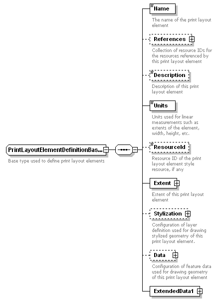
Each print layout element definition type is defined as a new PrintLayoutElementDefinition resource containing the definition of the particular type of print layout element. Here’s the base schema:
A sample print layout element definition for a map viewport is:
<?xml version="1.0" encoding="UTF-8"?>
<PrintLayoutElementDefinition version="2.0.0" xsi:noNamespaceSchemaLocation="PrintLayoutDefinition-2.0.0.xsd" xmlns:xsi="http://www.w3.org/2001/XMLSchema-instance">
  <MapViewportDefinition elementType="MapViewportDefinition">
    <Name>Main Viewport</Name>
    <References/>
    <Description>The main map viewport in the print layout</Description>
    <Units>inches</Units>
    <Extent>
      <Min>
        <X>1.0</X>
        <Y>1.0</Y>
        <Z>0.0</Z>
      </Min>
      <Max>
        <X>5.0</X>
        <Y>5.0</Y>
        <Z>0.0</Z>
      </Max>
    </Extent>
    <ExtendedData1/>
    <MapName>Sheboygan</MapName>
    <VisibleLayerNames/>
    <Locked>false</Locked>
    <On>true</On>
    <MapView>
      <Center>
        <X>0.0</X>
        <Y>0.0</Y>
        <Z>0.0</Z>
      </Center>
      <Height>180.0</Height>
      <Rotation>0.0</Rotation>
      <ViewDirection>
        <X>0.0</X>
        <Y>0.0</Y>
        <Z>0.0</Z>
      </ViewDirection>
      <ModelUnits/>
      <ExtendedData1/>
    </MapView>
  </MapViewportDefinition>
</PrintLayoutElementDefinition>
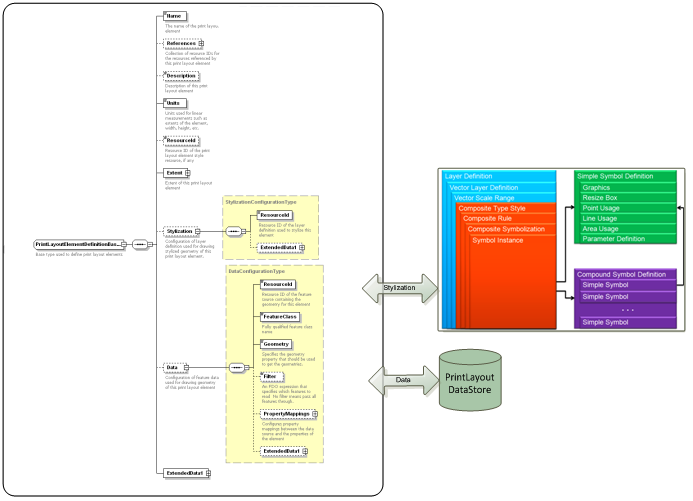
A print layout element definition may get the data it needs to elaborate its stylized geometry from the optional Stylization and Data properties. The Data property provides enough information to access all the data necessary to describe the geometry and attributes of the FDO features that are used to represent print layout data.
The Data property includes a resource id that corresponds to the feature source definition defining the feature source for print element layout data. The FeatureClass property within the Data property describes the fully qualified feature class name of the print element layout data. The Data element also includes a property that identifies the Geometry property within the feature class, a Filter property to specify an FDO filter for the features to retrieve, and a set of property mappings. These property mappings typically are used for determining which column names in the feature class that is used for print layout element type map to which property in a print layout element type. For example, imagine a feature class named “NorthArrowFeatureClass” is used for storing north arrow print layout element data (a point feature class) with a column “GEOM” that corresponds to the geometry column and “ORIENTATION,” and a north arrow print layout element schema contains a Rotation property. Then, the north arrow resource Xml will contain the “GEOM” as a property in the Data property along with a property mapping collection that contains a source property called “ORIENTATION” whose source units could be “radians” and a target property called “Rotation”. This helps with north arrow realization updating the correct property value of the point feature whenever it is notified of a twist angle change in the viewport it is associated with.
The Stylization property refers to a resource id that corresponds to the layer definition containing stylization information for the print layout element data (described by Data property). Typically, this will include the composite type style but in general can include any capability we have today in a LayerDefinition schema. The composite type style can include composite symbolization comprising simple or compound symbol definitions.
A particular type of print layout element has a couple of choices when it comes to how it wants to describe its stylized geometry. The first choice is that it can use feature geometry as the main geometry of the element and use the layer definition symbology to further enhance the stylization aspects of the geometry. The second choice is that it can use the layer definition symbology as the primary means to describe its stylized geometry. A classic example for the second choice is a north arrow where the underlying feature would be a point feature with its insertion point coinciding with the north arrow insertion point and using an AutoCAD block defining the north arrow graphics as a symbol that would appear at the insertion point. For Grids and graticules, on the other hand, the better choice might be the first choice where the geometry might tend to be complicated enough to warrant needing actual features (one or more) of different types with simple or complex symbology.
The main reason for this seemingly unnecessary complex mechanism to draw stylized geometry has to do with the sharing of components and language already built into the Common Platform API. We currently use the Platform stylization engine that renders stylized geometry of any FDO feature set using a custom renderer and a layer definition at a particular scale. This pipeline is common to multiple applications. The Data and Stylization properties are just an artifact of the need to have FDO features for geometry of data to be drawn and Layer Definition for stylization of that data.
All the print layout elements can leverage the existing enhanced vector symbolization so we can ensure 100% visual and data fidelity across products. While there are attractive and native solutions, the print layout architecture refrains from using those solutions mainly for interoperable definitions and visual fidelity of print layouts.
A print layout element can reference one or more data sources. These data sources provide information that the print layout element needs. For example, a grid print layout element always needs to know which viewport it is drawing the grid on. The resource identifier for the map viewport will thus be contained within the References property. Another example is a viewport needs to know which map it needs to display in the viewport. Currently, we have an explicit property called MapName on the MapViewport resource, but the References property can point to the id of a Map Definition resource.
A print layout element can also reference a print layout element definition. As was alluded earlier, a print layout element definition contains values of common properties that multiple instances of a print layout element type can share.
The !ExtendedData1 property is added to preserve data added in a later version of the resource in a round-trip scenario.
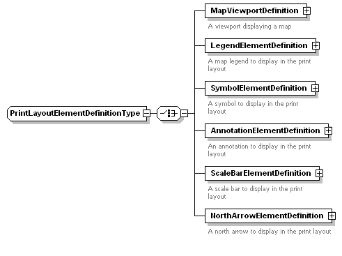
A print layout element can consist of any one of the several supported types as shown in the diagram below:
The schema version will be incremented, and new types will be added to this list as additional elements are supported in the future.
The following sections discuss the runtime common components that represent various print layout element types.
MgPrintLayoutElementBase class
This class represents the base class for all print layout elements. This is what is returned when a platform client realizes a print layout element using a product-specific print layout service object.
This class has properties that are separated out of the actual print layout element schema. For example, Visibility property is externalized from the print layout element itself so that it is controlled at runtime as opposed to hard-coding it. This class and its resource are very analogous to MgLayerBase and its associated layer definition resource. The MapDefinition resource actually defines the visibility of each layer and as such LayerDefinition itself does not contain a Visiblity property. Name is another such property.
The GetResourceId() method returns the resource identifier of the print layout element itself. Typically, this will be supplied at the construction time of MgPrintLayoutElementBase. This again is very similar to MgLayerBase.
The ForceRefresh() method exists to allow for products that can’t automatically respond to associated resource changes. Such a product is MapGuide where there can be no event support (this is not possible even internally since the site server and web server could be separated). In such products, a client that modifies a resource must invoke a method on the object that is affected by the resource change directly. In Layer API of Geospatial Platform, the ForceRefresh on MgLayerBase helps refresh the layer after its layer definition was modified.
PrintLayoutDefinition Resource schema
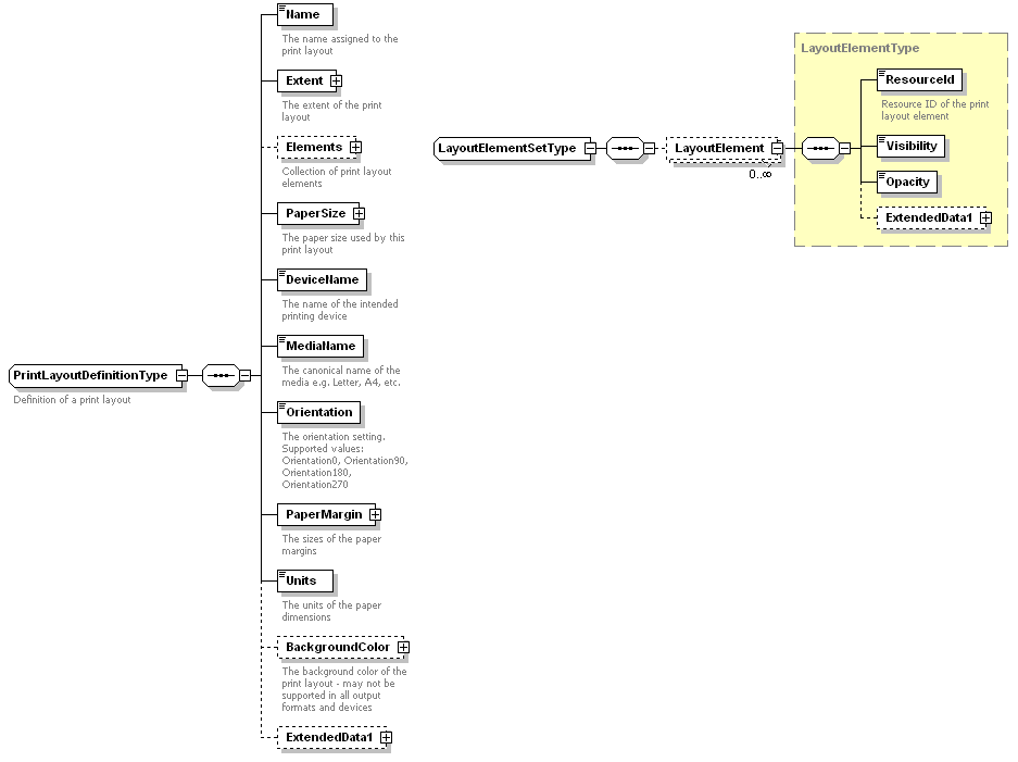
This class represents a runtime print layout just as MgLayerBase represents a runtime MapLayer. It is the container of all print layout elements. It is constructed using the resource identifier of a print layout definition resource that has information about the paper size, media name, etc. The diagram below shows a preliminary schema for the print layout.
The Elements collection contains the resource identifiers of the print layout elements that are contained within the print layout.
MgPrintLayout class
The realization of a print layout is an instance of MgPrintLayout class. In a 3rd Party application, it will be actually a concrete instance of and application specific type: XxxMapPrintLayout, which derives from MgPrintLayout. In MapGuide, it’ll be an instance of MapGuide-specific print layout realization class.
The GetElements() method returns a collection of actual runtime print layout element instances that are created for the Elements resource id collection. This is all very similar to MgMapBase having GetLayers() returning MgLayerCollection. Whenever a print layout element is added to or removed from the elements collection, a notification is sent out for listeners interested in the change. Those notifications are obviously on the XxxMapPrintLayout class since the Common Platform API does not handle events.
Print Layout Templates (Future Direction)
The idea of using templates to expedite and ease the process of creation of print layouts has been around and is used in such products as AutoCAD, Topobase and ESRI (ArcGis). However, the templates used are not inter-operable yet because of a lack of common definition of what that template will be. Typically, you’d create a print layout using an existing template that defines what type of print layout elements should appear, where and how. The ideas of reusing a print layout resource definition for print layout template has been slightly explored with the assumption that when the print layout elements within the template are realized during the creation of an actual print layout, the ambient information is automatically used without further indulgence from the user. For example, if a map viewport is included in the template, we won’t obviously have enough information about what map it will display, what the view of the map is, etc., but we would associate all map viewports with the current map and default view (entire map), for example, upon realization of a print layout using the template.
We need more research and elaboration to come up with details on how this would work uniformly across products.
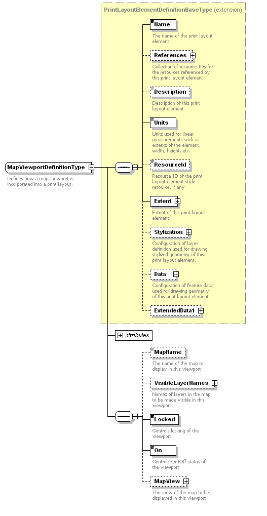
MapViewportDefinition Resource schema
The MapViewportDefinition resource represents a viewport displaying a map. It has all the information that is needed to define the extents, scale, rotation, map view characteristics, etc. Here’s the schema:
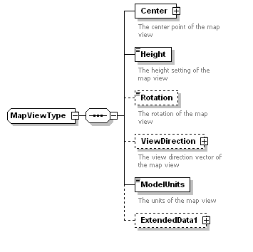
The MapViewportDefinition resource contains a MapName property, which is the name of the map the viewport is displaying. Note that this is only temporary until support for fully integrated Map Definition resources are in place accross all applications (This support will be outlined in a separate RFC to follow). When applications other than MapGuide truely support Map Definition, we will remove MapName property as we could add the resource id of the Map Definition resource in the References collection. Some of the properties (e.g., CenterPoint) shown above may not be needed, but those modifications will be made as the schema evolves. The VisibleLayers collection contains the names of Gis layers that need to be visible in the map viewport. The MapView property contains all the properties related to the view of the map. The Center property of MapView is the center point of the view in model units. The Height property specifies the height of the view in model units. The ModelUnits provide information about the units of the model space. The ViewDirection property fully specifies the direction vector of the view.
MgMapViewportBase class
The runtime representation of map viewport resource is MgMapViewportBase. The realization of this common interface in Thrirparty applications will be an application specific concrete class, i.e. XxxMapMapViewport.
Use Cases
Adding Required Data for Print Layout Element Creation
This use case is part of use cases involving creation of specific types of print layout elements. The sequence diagram below shows the various steps involved. The sequence assumes the client doesn’t have a data store for storing layout element data.
PRECONDITIONS
- None
STEPS
- Platform client gets the product-specific implementation of resource service.
- Client creates a new data store and builds a feature source definition referencing the created data store.
- Client adds the feature source definition to resource service by calling SetResource(fsId, fsXml). This data store will contain the print layout data that will be used to draw the geometry and stylize various aspects of the particular type of print layout element.
- If the client chooses to use an existing feature source connection, then the above step can be skipped.
- Client builds a layer definition, if applicable (for MapViewport resources, this step is not necessary) that references the feature source definition and adds it to Resource Service by calling SetResource.
Adding a Print Layout Element
This use case is part of use cases that realize a particular type of print layout element.
PRECONDITIONS
- Adding required data for map viewport creation use case
STEPS
- Client builds an Xml for a particular type of print layout element. In this Xml, he specifies the Data.ResourceId property to point to the feature source definition and the Stylization.ResourceId property to point to the layer definition created in the previous steps. He also sets the fully qualified feature class name of the print layout element data in Data.FeatureClass property.
- Client adds this Xml to Resource Service by calling SetResource(!printLayoutElementResId, !printLayoutElementXml)
- The Resource Service implementation creates an instance of PrintLayoutResourcesOwner if not already created and adds it to a named dictionary.
- The Resource Service calls AddResource on MapPrintLayoutResourcesOwner object.
- PrintLayoutResourcesOwner determines the type of the print layout element that is being added and creates an runtime representation object for the resource. In case of MapViewport resources, this would be MapViewportResource, inherited from MapResource class.
- PrintLayoutResourcesOwner then adds this runtime object to Resource Manager and also subscribes to Resource Manager events, if not already done.
API Scope
Print Layout Elements
In brief, the following APIs will be added:
- Runtime object models (MdfModel) in unmanaged and managed worlds for simplifying working with the new resource types including:
- MapViewport
- PrintLayoutElement
- PrintLayoutElementDefinition
- These will be similar to the other classes we have today in MdfModel. A parser will also be added similar to SAX2Parser we have today for parsing layer definitions. This parser will help build a runtime object model from a string.
- The Common Platform API will be extended with the following:
- A new service named MgPrintLayoutServiceBase
- New classes named:
- MgPrintLayoutElementBase
- MgMapViewportBase
- MgGrid
- MgGraticule
- MgPrintLayoutElementBaseDefinition
- MgPrintLayout
Migration from PrintLayout-1.0.0 to PrintLayoutDefinition-2.0.0
The design of the new schema is intended to provide a clear migration path from the old MapGuide PrintLayout format to the new format. The mappings of the various schema elements are defined below:
| PrintLayout-1.0.0 | PrintLayoutDefinition-2.0.0 | Comments |
| PageProperties:BackgroundColor | PrintLayoutDefinition:BackgroundColor | Optional in new schema – not supported in all formats or by all devices |
| LayoutProperties:ShowTitle | AnnotationElementDefinition referenced by PrintLayoutDefinition:Elements | A separate resource defining the font, text size, rotation etc. |
| LayoutProperties:ShowLegend | LegendElementDefinition referenced by PrintLayoutDefinition:Elements | A separate resource defining the map viewport for which to generate the legend |
| LayoutProperties:ShowScaleBar | ScaleBarElementDefinition referenced by PrintLayoutDefinition:Elements | A separate resource defining the map viewport for which to generate the scale bar |
| LayoutProperties:ShowNorthArrow | NorthArrowElementDefinition referenced by PrintLayoutDefinition:Elements | A separate resource defining the map viewport for which to generate the north arrow |
| LayoutProperties:ShowURL | AnnotationElementDefinition referenced by PrintLayoutDefinition:Elements | A separate resource defining the font, text size, rotation etc. |
| LayoutProperties:ShowDateTime | AnnotationElementDefinition referenced by PrintLayoutDefinition:Elements | A separate resource defining the font, text size, rotation etc. |
| LayoutProperties:ShowCustomLogos | See handling of CustomLogos element | |
| LayoutProperties:ShowCustomText | See handling of CustomText element | |
| CustomLogos | Zero or more SymbolElementDefinitions referenced by PrintLayoutDefinition:Elements | Each SymbolElementDefinition is a separate resource defining which symbol library and which symbol name to use for the logo, and optionally a rotation value to apply to the symbol. |
| CustomText | Zero or more AnnotationElementDefinitions referenced by PrintLayoutDefinition:Elements | Separate resources defining the font, text size, rotation etc. of each text item |
Proposed Milestone and Adoption Strategy
The above service and API changes will not be formally published in version 2.2 of the MapGuide Common Platform API. The current plan is to submit these changes as internal C++ APIs that are not universally exposed to the published .NET, Java or PHP APIs. The proposed release schedule for publishing the interfaces and services is tentatively scheduled for 2.3, however this has not been formally adopted. The intent of submitting these internal interfaces in 2.2 is to allow the concepts and ideas to be vetted and explored, with the results of these investigations feed back into the proposal as it structured for official release in 2.2 + 1.
Test Plan
Unit tests will be expanded or added as needed to test the proposed enhancements defined above.
Funding/Resources
Autodesk to provide resources / funding.
Addendum 1
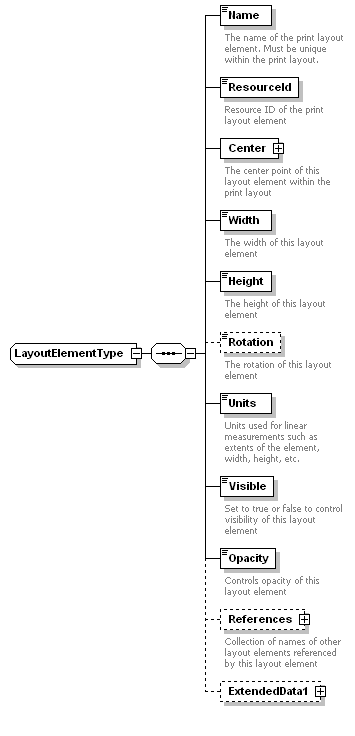
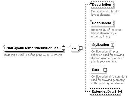
In order to support re-use of print layout element definitions in multiple print layouts, the schema has been updated so that the per-instance properties are stored in the LayoutElementType rather than in PrintLayoutElementDefinitionBaseType. This prevents a given element definition resource from being tied to a specific location and size in the parent layout.
The updated schema document is available here:
Print Layout Definition XSD Schema Document (Addendum 1)
The LayoutElementType complex type now looks like this:
And the PrintLayoutElementDefinitionBaseType looks like this:
Addendum 2
After some usage of the PrintLayout schema, several modifications will be required to ensure the correct definition and usage of the types contained within:
The updated schema elemnts are as follows:
PlatformCommon-1.1.0.xsd
The Red, Green, Blue and Alpha components of a Color definition should be defined as integers not doubles.
  <xs:complexType name="ColorType">
    <xs:sequence>
      <xs:element name="Red" type="xs:integer" default="0"/>
      <xs:element name="Green" type="xs:integer" default="0"/>
      <xs:element name="Blue" type="xs:integer" default="0"/>
      <xs:element name="Alpha" type="xs:integer" default="0"/>
    </xs:sequence>
  </xs:complexType>
PrintLayoutDefinition-2.0.0.xsd
The VisibleLayerNames property of MapViewportDefinitionType wil be renamed to HiddenLayerNames. In this manner, in applications where a large number of layers exist, the definition will only have to specify the layers that are to be hidden in the viewport. This is generally the shorter list and will help reduce processing time and document size.
  <xs:complexType name="MapViewportDefinitionType">
    <xs:annotation>
      <xs:documentation>Defines how a map viewport is incorporated into a print layout.</xs:documentation>
    </xs:annotation>
    <xs:complexContent>
      <xs:extension base="PrintLayoutElementDefinitionBaseType">
        <xs:sequence>
          <xs:element name="MapName" type="xs:string" default="" minOccurs="0">
            <xs:annotation>
              <xs:documentation>The name of the map to display in this viewport</xs:documentation>
            </xs:annotation>
          </xs:element>
          <xs:element name="HiddenLayerNames" type="LayerNameSetType" minOccurs="0">
            <xs:annotation>
              <xs:documentation>Names of layers in the map to be hidden in this viewport</xs:documentation>
            </xs:annotation>
          </xs:element>

    ...
    ...

      </xs:extension>
    </xs:complexContent>
  </xs:complexType>
Attachments (29)
-
PrintLayoutServiceBase.png
(23.2 KB
) - added by 16 years ago.
Print Layout Service Base Diagram
-
PrintLayoutElementType.PNG
(12.8 KB
) - added by 16 years ago.
Print Layout Element Type Definition
-
PrintLayoutElementTypeBlockDiagram.PNG
(91.9 KB
) - added by 16 years ago.
Print Layout Element Type Block Diagram
-
PrintLayoutElement.PNG
(14.0 KB
) - added by 16 years ago.
Print Layout Element
-
PrintLayoutElementInteractionDiagram.PNG
(43.7 KB
) - added by 16 years ago.
Print Layout Element Interaction Diagram
-
PrintLayoutType.PNG
(23.4 KB
) - added by 16 years ago.
Print Layout Type
-
PrintLayoutElementCollection.PNG
(32.2 KB
) - added by 16 years ago.
Print Layout Element Collection
-
MapViewportType.PNG
(20.1 KB
) - added by 16 years ago.
Map Viewport Type
-
MapViewType.PNG
(3.5 KB
) - added by 16 years ago.
Map View Type
-
AddRequiredDataUseCase.PNG
(19.2 KB
) - added by 16 years ago.
Adding required data for any print layout element creation
-
AddPrintLayoutElementUseCase2.PNG
(40.5 KB
) - added by 16 years ago.
Add print Layout Use Case
-
PrintLayoutOverview.PNG
(172.2 KB
) - added by 16 years ago.
Print Layout Overview
-
PrintLayout-1.1.0.xml
(13.4 KB
) - added by 16 years ago.
Print Layout Schema 1.1.0 (XSD)
-
PrintLayoutSchema.doc
(977.5 KB
) - added by 16 years ago.
Print Layout Schema Descriptive Documentation
-
PrintLayoutSchema.mht
(1.9 MB
) - added by 16 years ago.
Print Layout Schema Descriptive Documentation (HTML)
-
PrintLayoutSchema.pdf
(814.2 KB
) - added by 16 years ago.
Print Layout Schema Descriptive Documentation (PDF)
- PrintLayoutElementDefinitionBase.png (11.9 KB ) - added by 16 years ago.
- PrintLayoutElementDefinitionBaseBlockDiagram.png (73.5 KB ) - added by 16 years ago.
- PrintLayoutElementDefinitionType.png (3.9 KB ) - added by 16 years ago.
- PrintLayoutDefinitionType.png (20.2 KB ) - added by 16 years ago.
- MapViewType2.png (3.3 KB ) - added by 16 years ago.
- MapViewportDefinitionType.png (12.7 KB ) - added by 16 years ago.
- PrintLayoutDefinition-2.0.0.doc (466.2 KB ) - added by 16 years ago.
- PrintLayoutDefinition-2.0.0.mht (2.9 MB ) - added by 16 years ago.
- PrintLayoutDefinition-2.0.0_Add1.xsd (23.6 KB ) - added by 16 years ago.
- PrintLayoutElementDefinitionBase_Add1.png (4.0 KB ) - added by 16 years ago.
- LayoutElementType_Add1.png (6.5 KB ) - added by 16 years ago.
- PlatformCommon-1.1.0.xsd (2.2 KB ) - added by 15 years ago.
- PrintLayoutDefinition-2.0.0.xsd (23.6 KB ) - added by 15 years ago.


