
| Version 16 (modified by , 15 years ago) ( diff ) |
|---|
MapGuide RFC 67 - Common Print Layout and Print Layout Elements
This page contains an change request (RFC) for the MapGuide Open Source project. More MapGuide RFCs can be found on the RFCs page.
Status
| RFC Template Version | 1.0 |
| Submission Date | June 18, 2009 |
| Last Modified | Greg Boone Friday Jun 18 10:42:00 2009 |
| Author | Greg Boone |
| Contributors | Reva Revadigar, Chris Claydon, Steve Dang |
| RFC Status | Under Construction |
| Implementation Status | |
| Proposed Milestone | 2.x |
| Assigned PSC guide(s) | Bruce Dechant |
| Voting History | |
| +1 | |
| +0 | |
| -0 | |
| -1 | |
| no vote |
Overview
After some analysis on the overall ability to write robust applications using the Print Layout and Print Layout Element definitions as currently defined for MapGuide in the Common Platform API, the current definitions were found to be somewhat limited in their usefulness for developing non-MapGuide applications. In general, it was found to be insufficient to be considered as a robust foundation for a Print Layout Service that would meet the needs of common component development across multiple product lines. The goal of the forthcoming proposal will be the definition of a new print layout schema and service that would replace the current design and provide a foundation for multi-application development moving forward in version 2.x of the Platform API.
Proposed Solution
To support common print layout elements, the general approach will be to develop a set of common definitions representing the schema of various print layout element types, the common components that embody those definitions, and supply the architecture for sharing these definitions and components accross application.
Print Layout and Print Layout Elements
The detailed schema containing the definitions of the print layout, print layout element, and print layout element definition can be found in the attached documents.
The XSD schema definition can be found in the attached Print Layout XSD Definition or in its associted documentation files in:
microsoft word format
html format
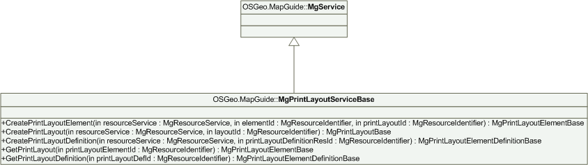
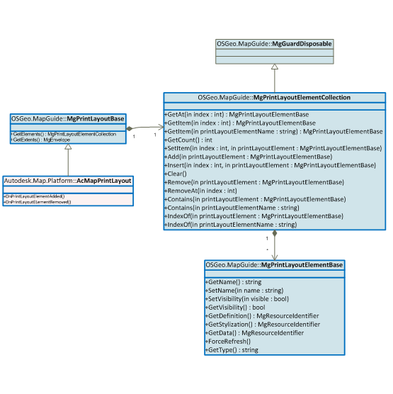
The print layout element design involves defining an entry point for creating print layout and its elements. This entry point is called MgPrintLayoutServiceBase.

This service can be accessed by the familiar entry point for services specific to products using the Common Platform API. For example, it can be accessed as:
MgPrintLayoutServiceBase printLayoutService = ServiceFactory::GetService(MgResourceType::PrintLayout);
MgPrintLayoutServiceBase Class
Here are the principal methods of MgPrintLayoutServiceBase:
CreatePrintLayoutElement
Accepts a resource identifier of the print layout element Xml, and optionally the resource identifier of print layout Xml. It returns the realization of a print layout element in the form of MgPrintLayoutElementBase. The actual realized object depends on the product and the type of print layout element.
For example, if a client wants to create a map viewport, he supplies the resource identifier of map viewport resource Xml. The method returns MgMapViewportBase, which is derived from MgPrintLayoutElementBase. In an application, the method returns XxxMapMapViewport, which inherits from MgMapViewportBase. In MapGuide, the method might return an object of a derived class of MgMapViewportBase similar to XxxMapMapViewport. The caller can use this object to manipulate state on the object.
CreatePrintLayout
Accepts a resource identifier of the print layout Xml and returns MgPrintLayout. It returns the realization of a print layout in the form of MgPrintLayout. The actual realized object depends on the product. For example, it returns XxxMapPrintLayout, which is inherited from MgPrintLayout. In MapGuide, it returns a similar derived object from MgPrintLayout.
CreatePrintLayoutDefinition
Accepts a resource identifier of the print layout element definition. It returns the realization of a print layout element definition in the form of MgPrintLayoutDefinition. The actual realized object depends on the product and the print layout definition. The print layout element definition resources afford reuse of common traits of print layout elements. For example, one or more scale bars might use a common line style, fill color, etc. A print layout element definition affords such reuse. The method returns an MgPrintLayoutElementBaseDefinition. Each type of print layout element that has a need to share a number of traits among multiple instances of the type can define its own print layout definition and reference it from the print layout element resource.
GetPrintLayoutElement
Accepts the identifier of an already existing print layout element resource. It returns the realized print layout element. The actual realized object depends on the product and the type of print layout element.
GetPrintLayoutDefinition
Accepts the identifier of an already existing print layout definition resource. It returns the realized print layout element definition. The actual realized object depends on the product and the type of print layout definition.
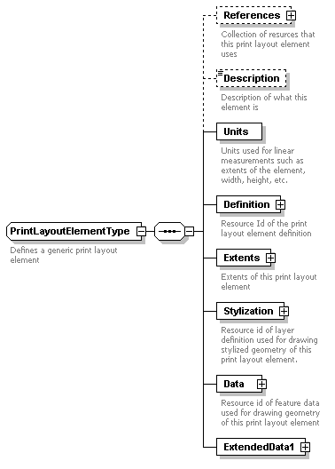
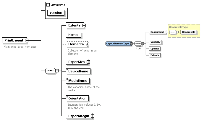
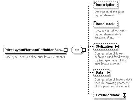
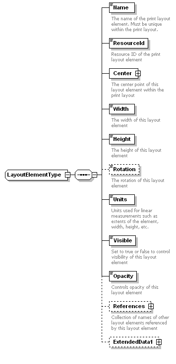
PrintLayoutElement Resource Schema
Each print layout element type is defined as a new PrintLayoutElement resource containing definition of the particular type of print layout element. Here’s the schema:

A sample print layout element for map viewport is:
<?xml version="1.0" encoding="UTF-8"?>
<LayoutElement xmlns:xsi="http://www.w3.org/2001/XMLSchema-instance"
xsi:noNamespaceSchemaLocation="Schema\PrintLayoutSchema-1.1.0.xsd">
	<MapViewport>
		<Extents>
		…
		</Extents>
		…
	</MapViewport>
</LayoutElement>
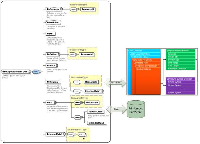
A print layout element gets the data it needs to elaborate its stylized geometry from both Stylization property and Data property. The Data property provides enough information to access all the data necessary to describe the geometry and attributes of the FDO features that are used to represent print layout data.

The Data property includes a resource id that corresponds to the feature source definition defining the feature source for print element layout data. The FeatureClass property within the Data property describes the fully qualified feature class name of the print element layout data.
The Stylization property refers to a resource id that corresponds to the layer definition containing stylization information for the print layout element data (described by Data property). Typically, this will include the composite type style but in general can include any capability we have today in a LayerDefinition schema. The composite type style can include composite symbolization comprising simple or compound symbol definitions.
A particular type of print layout element has a couple of choices when it comes to how it wants to describe its stylized geometry. The first choice is that it can use feature geometry as the main geometry of the element and use the layer definition symbology to further enhance the stylization aspects of the geometry. The second choice is that it can use the layer definition symbology as the primary means to describe its stylized geometry. A classic example for the second choice is a north arrow where the underlying feature would be a point feature with its insertion point coinciding with the north arrow insertion point and using an AutoCAD block defining the north arrow graphics as a symbol that would appear at the insertion point. For Grids and graticules, on the other hand, the better choice might be the first choice where the geometry might tend to be complicated enough to warrant needing actual features (one or more) of different types with simple or complex symbology.
The main reason for this seemingly unnecessary complex mechanism to draw stylized geometry has to do with the sharing of components and language already built into the Common Platform API. We currently use the Platform stylization engine that renders stylized geometry of any FDO feature set using a custom renderer and a layer definition at a particular scale. This pipeline is common to multiple applications. The Data and Stylization properties are just an artifact of the need to have FDO features for geometry of data to be drawn and Layer Definition for stylization of that data.
All the print layout elements can leverage the existing enhanced vector symbolization so we can ensure 100% visual and data fidelity across products. While there are attractive and native solutions, the print layout architecture refrains from using those solutions mainly for interoperable definitions and visual fidelity of print layouts.
A print layout element can reference one or more data sources. These data sources provide information that the print layout element needs. For example, a grid print layout element always needs to know which viewport it is drawing the grid on. The resource identifier for the map viewport will thus be contained within the References property. Another example is a viewport needs to know which map it needs to display in the viewport. Currently, we have an explicit property called MapName on the MapViewport resource, but the References property can point to the id of a Map Definition resource.
A print layout element can also reference a print layout element definition. As was alluded earlier, a print layout element definition contains values of common properties that multiple instances of a print layout element type can share.
The !ExtendedData1 property is added to preserve data added in a later version of the resource in a round-trip scenario.
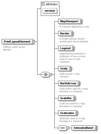
A print layout element can consist of any one of the several supported types as shown in the diagram below:

The list is not limited to just the types shown above. We would add more in the future.
The Print Layout architecture also allows for creation of print layout elements that are used as adornments and decorations on other print layout elements. The decorators are elements that might alter the stylized geometry of their target print layout element and adorners simply draw their own stylized geometry around their target print layout elements. An example of an adorner is a Border print layout element type that can draw a fancy border with symbols around a map viewport print layout element. These aspects allow for powerful composition of print layout elements.
Implications
Test Plan
Funding/Resources
Attachments (29)
-
PrintLayoutServiceBase.png
(23.2 KB
) - added by 15 years ago.
Print Layout Service Base Diagram
-
PrintLayoutElementType.PNG
(12.8 KB
) - added by 15 years ago.
Print Layout Element Type Definition
-
PrintLayoutElementTypeBlockDiagram.PNG
(91.9 KB
) - added by 15 years ago.
Print Layout Element Type Block Diagram
-
PrintLayoutElement.PNG
(14.0 KB
) - added by 15 years ago.
Print Layout Element
-
PrintLayoutElementInteractionDiagram.PNG
(43.7 KB
) - added by 15 years ago.
Print Layout Element Interaction Diagram
-
PrintLayoutType.PNG
(23.4 KB
) - added by 15 years ago.
Print Layout Type
-
PrintLayoutElementCollection.PNG
(32.2 KB
) - added by 15 years ago.
Print Layout Element Collection
-
MapViewportType.PNG
(20.1 KB
) - added by 15 years ago.
Map Viewport Type
-
MapViewType.PNG
(3.5 KB
) - added by 15 years ago.
Map View Type
-
AddRequiredDataUseCase.PNG
(19.2 KB
) - added by 15 years ago.
Adding required data for any print layout element creation
-
AddPrintLayoutElementUseCase2.PNG
(40.5 KB
) - added by 15 years ago.
Add print Layout Use Case
-
PrintLayoutOverview.PNG
(172.2 KB
) - added by 15 years ago.
Print Layout Overview
-
PrintLayout-1.1.0.xml
(13.4 KB
) - added by 15 years ago.
Print Layout Schema 1.1.0 (XSD)
-
PrintLayoutSchema.doc
(977.5 KB
) - added by 15 years ago.
Print Layout Schema Descriptive Documentation
-
PrintLayoutSchema.mht
(1.9 MB
) - added by 15 years ago.
Print Layout Schema Descriptive Documentation (HTML)
-
PrintLayoutSchema.pdf
(814.2 KB
) - added by 15 years ago.
Print Layout Schema Descriptive Documentation (PDF)
- PrintLayoutElementDefinitionBase.png (11.9 KB ) - added by 15 years ago.
- PrintLayoutElementDefinitionBaseBlockDiagram.png (73.5 KB ) - added by 15 years ago.
- PrintLayoutElementDefinitionType.png (3.9 KB ) - added by 15 years ago.
- PrintLayoutDefinitionType.png (20.2 KB ) - added by 15 years ago.
- MapViewType2.png (3.3 KB ) - added by 15 years ago.
- MapViewportDefinitionType.png (12.7 KB ) - added by 15 years ago.
- PrintLayoutDefinition-2.0.0.doc (466.2 KB ) - added by 15 years ago.
- PrintLayoutDefinition-2.0.0.mht (2.9 MB ) - added by 15 years ago.
- PrintLayoutDefinition-2.0.0_Add1.xsd (23.6 KB ) - added by 15 years ago.
- PrintLayoutElementDefinitionBase_Add1.png (4.0 KB ) - added by 15 years ago.
- LayoutElementType_Add1.png (6.5 KB ) - added by 15 years ago.
- PlatformCommon-1.1.0.xsd (2.2 KB ) - added by 15 years ago.
- PrintLayoutDefinition-2.0.0.xsd (23.6 KB ) - added by 15 years ago.