
| Version 16 (modified by , 15 years ago) ( diff ) |
|---|
MapGuide RFC 59 - Add TIN layer type in Layer Defination Schema
This page contains an change request (RFC) for the MapGuide Open Source project. More MapGuide RFCs can be found on the RFCs page.
Status
| RFC Template Version | (1.0) |
| Submission Date | (Date/Time submitted) |
| Last Modified | Evan Yan Timestamp |
| Author | Evan Yan |
| RFC Status | draft |
| Implementation Status | under development |
| Proposed Milestone | (e.g. 1.1, 1.3, 2.1) |
| Assigned PSC guide(s) | (when determined) |
| Voting History | (vote date) |
| +1 | |
| +0 | |
| -0 | |
| -1 | |
| no vote |
Overview
The purpose of this RFC is to add a new type of layer element in Layer Definition XML schema for TIN (Triangulated Irregular Networks). TIN is used to simulate triangle based terrain. It has many characteristics that are different from vector data and raster data, it’s necessary to create a new layer type for TIN.
Motivation
There are several kinds of data as vector and raster. TIN is another kind of data that can describe terrain model. Some products such as Oracel Spacial support TIN data. However, MapGuide does not support it yet. So, currently we cannot show a real TIN surface in MapGuide.
Adding TIN layer schema will make it easier to support TIN layer and there will be a real TIN surface. We can see points, edges and faces if we zoom into the surface.
In future, FDO Provider may support TIN.
Proposed Solution
The proposed solution contains modifications to the Layer Definition XML schema. We will create following elements for the MapGuide LayerDefinition XML schema.
| Type | * Annotation * |
| TinLayerDefinitionType | A layer for tin data. |
| TinScaleRangeType | The stylization for a specified scale range. |
| TinColorRuleType | Encapsulate a style for a tin source. |
| TinFaceType | Style rule for a face type. |
| TinHillShadeType | Specifies how to shade given a band and a light source. |

- BaseLayerDefinitionType is an existing common type for all layer types.
- FeatureName and Geometry are the same as in Vector/Grid layer.
- Filter element is an FDO expression for the ColorRule. Any features that pass this filter are styled using this rule's stylization. We can stylize TIN surface by elevation, slope and aspect. For example, this surface is stylized with XML snippet as below:
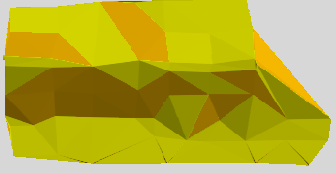
<ColorStyle> ... <ColorRule> <LegendLabel> 0 to 18</LegendLabel> <Filter>(Slope(1) >= 0) AND (Slope(1) < 18)</Filter> <Color> <ExplicitColor>FFFFFF00</ExplicitColor> </Color> </ColorRule> <ColorRule> <LegendLabel> 18 to 36</LegendLabel> <Filter>(Slope(1) >= 18) AND (Slope(1) < 36)</Filter> <Color> <ExplicitColor>FFFFBF00</ExplicitColor> </Color> </ColorRule> ... <ColorRule> <LegendLabel>{DEFAULT}</LegendLabel> <Color> <ExplicitColor>FF006423</ExplicitColor> </Color> </ColorRule> </ColorStyle>

- The type for TinScaleRange is TinScaleRangeType.
- MinScale and MaxScale elements are used to control the scale range.
- Elevation element includes two elevation related factors: ZeroValue element is the user defined zero value, Defaults to 0 if not specified; ScaleFactor element determines how to scale the elevation. Defaults to 1.
- The element type that specifies the style of Point and Edge in the layer definition schema is CompositeTypeStyle which already exists in schema, see MapGuide RFC 14 for details.
- The element type of Face is TinFaceType, see details as follow.

- HillShade element contains Azimuth and Altitude of the sun.
- TinColorRuleType likes GridColorRuleType of gird layer.
Example:
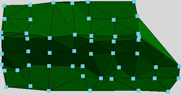
Here is a TIN surface:
We can see all points and triangles in the surface.

The XML snippet is would be:
<TinLayerDefinition>
<ResourceId>fsd://Tin_1</ResourceId>
<FeatureName>tin: Surface</FeatureName>
<Geometry>Tin</Geometry>
<TinScaleRange>
<MaxScale>10000</MaxScale>
<Elevation>
<ZeroValue>100</ZeroValue>
<ScaleFactor>1.5</ScaleFactor>
</Elevation>
<Point>
<CompositeTypeStyle >...</CompositeTypeStyle >
<ShowInLegend>true</ShowInLegend>
</Point>
<Edge>
<CompositeTypeStyle >...</CompositeTypeStyle >
<ShowInLegend> true </ShowInLegend>
</Edge>
<Face>
<HillShade>
<Azimuth>45</Azimuth>
<Altitude>45</Altitude>
</HillShade>
<ColorRule>
<LegendLabel>-1.79e+308 to 1.79e+308</LegendLabel>
<Filter>(Height(1) > -1.7976931348623158e+308) AND (Height(1) < 1.7976931348623158e+308)</Filter>
<!-- or it could be:
<Filter>(Aspect(1) > 0) AND (Aspect(1) < 20)</Filter>
or:
<Filter>(Slope(1) > 0) AND (Slope(1) < 20)</Filter>
-->
<Color>
<ExplicitColor>FF00FF00</ExplicitColor>
</Color>
</ColorRule>
<ColorRule>
<LegendLabel>{DEFAULT}</LegendLabel>
<Color>
<ExplicitColor>FF006423</ExplicitColor>
</Color>
</ColorRule>
</Face>
</TinScaleRange>
<TinScaleRange>
...
</TinScaleRange>
...
</TinLayerDefinition>
Implications
The new TIN layer definition will have an impact on the LayerDefinition XML schema. Backwards compatibility should be maintained and will not break any existing applications. That is to say, applications with later version can completely open files created by applications with former version, while applications with former version should ignore TIN layer when opening file created by applications with later version. Documentation will need to be updated for the new functionality.
Test Plan
- Unit tests should include creating TIN layers.
- Backward compatibility should be tested. Files created by new application should not break existing applications.
Funding/Resources
Autodesk to provide resources/funding.
Attachments (5)
-
LayerDefinition-1.4.0.xsd
(59.8 KB
) - added by 15 years ago.
TIN layer was added to the schema.
- TinLayerDefinitionType.bmp (1.3 MB ) - added by 15 years ago.
- TinFaceType.bmp (937.3 KB ) - added by 15 years ago.
- TinSurface_Points_And_Triangles.bmp (527.7 KB ) - added by 15 years ago.
- stylize_by_slope.bmp (171.3 KB ) - added by 15 years ago.