
| Version 25 (modified by , 16 years ago) ( diff ) |
|---|
MapGuide RFC 51 - Raster Re-projection
This page contains an change request (RFC) for the MapGuide Open Source project. More MapGuide RFCs can be found on the RFCs page.
Status
| RFC Template Version | (1.0) |
| Submission Date | July 14, 2008 |
| Last Modified | Tony Fang Timestamp |
| Author | Tony Fang |
| RFC Status | adopted |
| Implementation Status | pending |
| Proposed Milestone | 2.1 |
| Assigned PSC guide(s) | Tom Fukushima |
| Voting History | August 22, 2008 |
| +1 | Tom, Bruce, Andy, Jason |
| +0 | |
| -0 | |
| -1 | |
| no vote | Paul, Bob, Haris |
Overview
This is a proposal to add an efficient raster re-projection algorithm that is based on tessellating an image into smaller triangles and re-projecting the triangles.
Motivation
MapGuide does not currently support any form of raster re-projection. If a user has a raster feature source, it can only be displayed in a MapGuide map that uses the same coordinate system as the raster data.
Previously, in order for application developers to use images in multiple coordinate systems, they needed to create copies of the images in each coordinate system. The re-projection capability that we are adding will allow developers to not have to have multiple versions of the same image (re-projected to different coordinate systems) at the cost of about 25% degradation in performance.
Proposed Solution
We will use a tessellation algorithm to re-project the raster data from one coordinate system (CS) to another.
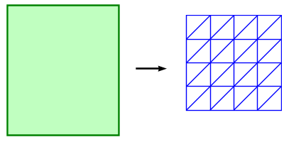
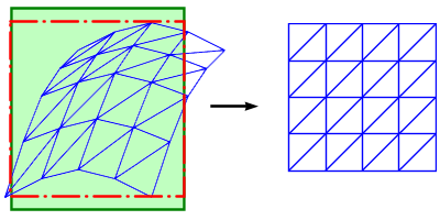
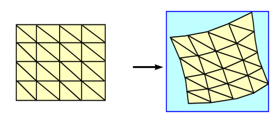
In Figure 1, the green rectangle represents the original raster image. The blue mesh represents the extents of the viewport (or map), divided into a set of triangular regions. The purpose of the algorithm is to re-project the appropriate triangular sections of the original image into the equivalent parts of the mesh.

|
| Figure 1. The left side shows the raster image (green rectangle) in it's own CS. The right side shows the blue mesh of uniform triangles created in device space in the viewport CS. |
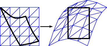
We must first determine how much of the original image is required by projecting the extents of the viewport (or map) into the image's CS. The intersection of the re-projected extents with the original image extents yields our desired clipped image (red outline, Figure 2).
Each point in the triangle mesh is transformed from device space, to the viewport's CS, to the image's CS, and then to device space. A texture map is created from the two triangle meshes.

|
| Figure 2. The blue mesh of triangles has been transformed into the raster image's CS. |
The image will then be rendered using the texture map created from the two triangle meshes (Figure 3). Because the triangle mesh is in device space, choosing its size guarantees you a minimum level of accuracy: the error in the re-projected image will never be greater than the size of the individual triangles.

|
| Figure 3. The raster image is rendered into the viewport using the texture map. |
The balance between performance and accuracy of the transformation is controlled by the number of triangles created for each raster. The configuration setting will control the grid size and thus the number of triangles created. The configuration will be handled by the serverconfig.ini.
The category and setting names for this configuration are:
[RenderingServiceProperties]
# *****************************************************************************
# R E N D E R I N G  S E R V I C E
#
# Property Name                    Description
# -----------------------------------------------------------------------------
# RasterGridSize                   Size of raster re-projection grid in pixels
# *****************************************************************************
RasterGridSize = 100
Descriptive error messages will be logged to handle invalid configuration settings, invalid data, unsupported transformations etc.
In keeping with MapGuide’s current behavior, if the re-projection fails for any reason, the map will still be rendered and returned, using any other layers that it contains, and the failed layer(s) will be skipped.
We will add an optimization if the re-projection is a simple datum shift. The image will simply be shifted, and the advanced algorithm will not be invoked.
We will support re-projecting raster in drawing sources.
Implications
WMS is also a raster feature source and will be affected by this algorithm.
The AGG and DWF Renderers will support raster re-projection.
GD Renderer support is on hold pending RFC 52 - Remove GD Renderer.
Test Plan
Unit tests should cover:
- The most common raster image formats (ECW, MrSid, TIFF)
- Re-projections between each of the main coordinate system types
Unit tests should also validate that error conditions are handled gracefully.
Funding/Resources
Autodesk
Addendum
When we came to implement this proposal, it became apparent that it would be more efficient to generate the grid in the raster coordinate system and transform it into the map coordinate system, rather than the other way round (as originally proposed). A description of the new method follows:
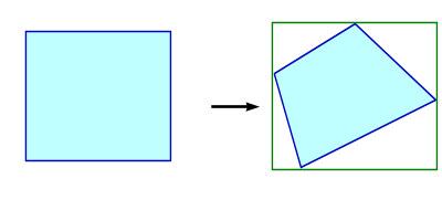
In Figure 1, the blue rectangle represents the current map (or viewport) extents. The extents are converted from the map coordinate system into the raster coordinate system in order to determine the new extents in the raster CS (green rectangle).

|
| Figure 1. Conversion of map (or viewport) extents into raster coordinate system. |
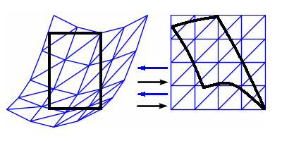
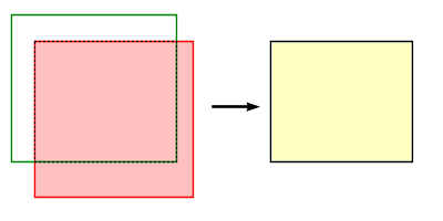
The intersection of the raster extents (pink) with the map extents (green) is then calculated in the raster coordinate system. And this part of the raster image is retrieved from the provider (yellow).

|
| Figure 2. Intersection of map and raster in raster CS. |
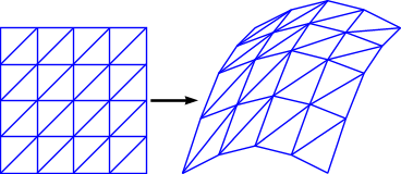
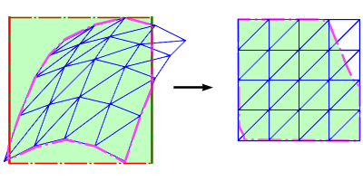
The raster image is then divided into a mesh of tesselating triangles. The vertices of the mesh are transformed from raster pixel coordinates into the raster coordinate system coordinates, then into the map (or viewport) coordinate system coordinates, and finally into map pixel coordinates, to create a transformed non-uniform mesh. Each triangle from the source raster is then rendered into the corresponding triangular section in the destination mesh to produce the transformed raster image.

|
| Figure 3. The raster image is rendered into the viewport using the transformation mesh. |
Attachments (9)
- raster_reprojection.PNG (11.6 KB ) - added by 16 years ago.
- raster_reprojection_viewport.PNG (12.5 KB ) - added by 16 years ago.
- raster_reprojection_viewport2.PNG (14.9 KB ) - added by 16 years ago.
- raster_reprojection_viewport3_1.PNG (3.2 KB ) - added by 16 years ago.
- raster_reprojection_viewport3_2.PNG (19.0 KB ) - added by 16 years ago.
- raster_reprojection_viewport3_3.PNG (24.6 KB ) - added by 16 years ago.
- MapRasterIntersection.png (2.0 KB ) - added by 16 years ago.
- MapToLayerCS.png (4.2 KB ) - added by 16 years ago.
- MeshReprojection.png (18.4 KB ) - added by 16 years ago.
Download all attachments as: .zip