
| Version 18 (modified by , 17 years ago) ( diff ) |
|---|
MapGuide 29 - MDF Schema Changes for Stylization
This page contains a change request (RFC) for the MapGuide Open Source project. More MapGuide RFCs can be found on the RFCs page.
Status
| RFC Template Version | 1.0 |
| Submission Date | September 7, 2007 |
| Last Modified | Walt Welton-Lair Timestamp |
| Author | Walt Welton-Lair |
| RFC Status | draft |
| Implementation Status | pending |
| Proposed Milestone | 2.0 |
| Assigned PSC guide(s) | (when determined) |
| Voting History | (vote date) |
| +1 | |
| +0 | |
| -0 | |
| -1 |
Overview
A few omissions in our new symbolization schemas have been identified. This RFC describes the proposed schema changes which address the issues.
Motivation
Legend Labels for Multi-Variate Theming
In the new symbolization we have symbol definitions which define parameters, and symbol instances which define overrides - constant values or expressions - for these parameters. For MapGuide 2.0 we have proposed to add new expression functions which can be used to specify themes (see MapGuide RFC 32). Multi-variate theming is achieved by using these new expression functions in parameter overrides. No schema change is needed to support the new expression functions - expressions are just strings and the parameter overrides are string properties. Multi-variate theming does add some complexity when it comes to legend labels, and this is where additional information in the schema is needed.
The current layer definition schema defines a legend label per style rule. Today when we create a theme we generate multiple style rules, and the legend label for each rule is set appropriately. The new multi-variate theming approach, however, uses expressions and not rules to define the theme. With the current schema this means only one legend label is available for all the themes, and this is inadequate. The proposed schema change is to therefore include additional theme information to the parameter override elements.
For this release it will be sufficient to add two pieces of information: a theme description and a default theme category format. Any parameter override whose value is set to a theming expression would also set these properties. The legend generation code can then use this information to generate appropriate labels for each theme / theme category. The theme description is a string that would be displayed the same as it's entered. The theme category format is a string which includes a mix of formatting codes and text, and these can appear in any order. Three codes will be supported: <min>, <max>, and <value>. The <min> and <max> codes are used with themes where each category corresponds to a range of values. Some example category format strings:
- "<min> to <max>"
- "Parcel value: <min> - <max> Euros"
- "<min> <= Population < <max>"
The <value> code is used with themes that assign a single value to each category. Some additional example format strings:
- "Zip code: <value>"
- "Zone <value>"
Symbol Instance Rendering Passes
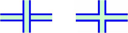
The new symbolization introduced the concept of rendering passes. For a given layer a rendering pass corresponds to an iteration by the stylization code over that layer's features. The default is to render with one pass (pass 0): we iterate once over all the features, and for each feature we stylize / draw it using all the symbols. Usually this gives the desired behavior, but not always. The common example where this doesn't work is when you want to draw a thin line on top of a thick line, and have "merging" behavior where features intersect:

This image shows the behavior for two intersecting features which are styled using a thick line and then a thin line. At left is the result if we draw with one pass: the thick line for the vertical feature is drawn on top of the thin line for the horizontal feature. At right is the result if we use two passes: we draw all the features once with the thick line, and then draw them all again using the thin line.
The current symbol definition schema allows rendering passes (RP's) to be specified in a CompoundSymbolDefinition. The example above could be done using a CompoundSymbolDefinition containing thick and thin line style symbols, with the RP's for the thick / thin lines set to 0 / 1.
The benefit of this approach is that the RP information is stored with the symbol definition: there's no need to re-specify it when referencing this symbol in a layer.
The approach, however, does have some drawbacks:
- Rendering passes can only be used by defining compound symbol definitions
- Mixing compound symbols that define RPs with other symbols is problematic
Here's an example that clarifies the latter drawback. I want to create a layer which shows roads and pedestrian walkways. I have custom symbols already defined for the roads and walkways - both are compound symbols that have thick and thin line styles defined using RP 0 and 1. I set up my layer so that features of type "road" are styled using the Road symbol, while features of type "walkway" are styled using the Walkway symbol. I also have the requirement that walkways need to draw on top of roads. With the symbols defined as is this won't work. The first rendering pass - pass 0 - will iterate over all features and draw the thick Road lines and then the thick Walkway lines. The second rendering pass will then draw the thin Road lines and the thin Walkway lines. In places where walkway features intersect road features, the thin Road lines drawn in RP 1 will end up drawing on top of the thick Walkway lines drawn in RP 0.
We could easily fix this by editing the Walkway symbol to use RP 2 and 3, but then this also affects other layers in other maps that use the Walkway symbol. I may then have to adjust RP values for yet other symbols. Or maybe the Walkway symbol is part of a symbol library that I purchased, and I don't want to change it.
Another use case where the current schema's support for rendering passes is insufficient is when a user wants to build up a composite line style from predefined symbols. MapGuide Studio, for example, provides UI to do this. If the user only works with SimpleSymbolDefinitions, then this could be done by creating an inlined CompoundSymbolDefinition that references all of the simple symbols and sets the appropriate RP values. This approach doesn't work, however, if the user wants to include a CompoundSymbolDefinition in his composite style. That's because we can't add a reference to his CompoundSymbolDefinition in the inlined CompoundSymbolDefinition - by design compound symbols can only reference simple symbols.
The proposed solution to this is simple: add a RenderingPass element to SymbolInstance, so that we now have two levels of rendering passes. The algorithm is straightforward. We start the layer stylization with symbol instance rendering pass 0, and only instances with their RP set to 0 are enabled for this pass. We then stylize / draw using the symbol definitions for this set of instances, making as many sub-rendering passes as necessary based on the RP values of these symbol definitions. We then move to the next symbol instance rendering pass. Again, we only consider symbol instances / symbol definitions for this pass, and do sub-rendering passes as necessary. This is continued until all necessary symbol instance RPs have been made.
With this approach, I would configure the layer for the road / walkway example like the following:
- SymbolInstance A
- reference to Road symbol
- instance RP set to 0
- SymbolInstance B
- reference to Walkway symbol
- instance RP set to 1
At stylization time, this would result in the following sequence of passes:
- SymbolInstance RP 0
- Road symbol RP 0
- Road symbol RP 1
- SymbolInstance RP 1
- Walkway symbol RP 0
- Walkway symbol RP 1
Angular Offset Relative to Feature Geometry
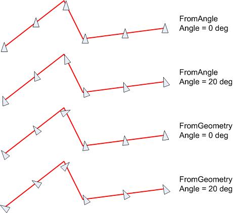
The symbol definition schema currently includes support for specifying whether symbol angles are absolute or are computed from the geometry. This is done via the AngleControl element in PointUsage, LineUsage, and AreaUsage. If AngleControl is set to 'FromAngle' then we use the value of the Angle element when drawing the symbol, while if AngleControl is set to 'FromGeometry' then we use the feature geometry to compute the draw angle. In the latter case we ignore the Angle element.
The proposed change in behavior is that in the case of 'FromGeometry' we now use the Angle element to specify the additional amount to rotate the feature relative to the angle computed from the geometry.
In the case of point features this change makes no difference - the computed angle of a point is zero. The behavior only changes for line and area features. For line features the computed angle is the angle of the polyline at the symbol insertion point. With the proposed change a user would be able to specify that his/her symbol be rotated a given amount relative to the polyline. For area features the computed angle is the angle of the longest edge. The same behavior change applies here.
Here's an image showing the different behaviors for lines:

SymbolInstance Usage and Geometry Contexts
A symbol definition can contain multiple usages - PointUsage, LineUsage, and AreaUsage - which describe how the symbol behaves in the context of 0D, 1D, and 2D geometry. PointUsage can be used in the context of point, polyline, and polygon features. In the case of polylines and polygons you simply need to pick a point on the polyline / polygon at which to draw the symbol (e.g. the mid-point or centroid). LineUsage can be used in the context of polyline and polygon features. In the case of polygons, the LineUsage applies to the polygon edge. AreaUsage can only be used in the context of polygon features.
Now consider the following scenario. You have a polygon layer and you want to define both the fill and edge style using some predefined symbols. Assume each symbol definition has all three usages defined. To configure your layer you create two SymbolInstances, each referencing the appropriate symbol definition. You want the first symbol to be used for the fill style - so have its AreaUsage be the active usage - and the second symbol to be used for the edge style - so have its LineUsage be the active usage. Using the current schema it's not possible to do this. There's no place to put information that specifies which usage in a symbol definition should be the active usage.
The proposed solution to this is to add an optional UsageContext element to SymbolInstance that specifies which usage type should be the active usage. In the above example you would set the UsageContext for the first SymbolInstance to Area and for the second SymbolInstance to Line.
Now let's take this example further. Suppose the feature source for your layer contains multiple geometry types: points, polylines, and polygons. You need to be able to control the stylization for each of these types. You have some predefined symbols you'd like to use for each type: a symbol with a PointUsage for the points (symbol A), one with a LineUsage for the polylines (symbol B), one with a LineUsage for the polygon edges (symbol C), and a final one with an AreaUsage for the polygon fill (symbol D). To configure your layer you create SymbolInstances referencing each of these symbols. As described above, you set the UsageType on each SymbolInstance to remove any redundancy about which usage in the symbol definition should be active. Now the code starts drawing features from the layer. The only applicable symbol for point features is symbol A, so those features draw as expected. For polyline features we have a problem though: symbols A, B, and C can all be used to style polyline features. The active usage for symbol A is Point, and therefore we could draw a single instance of symbol A at the polyline mid-point. The active usages for symbols B and C is Line, and therefore we would use those symbols as line styles for that polyline. (The active usage for symbol D is Area, and that doesn't apply to polylines.) The same problem happens with polygon features: in this case all four symbols can be used to style polygon features. The basic problem here is that there's no place in the schema to specify which geometry type a symbol instance should apply to. There's no way for the code to automatically determine which symbols should be used for different geometry types.
The proposed solution to this is to add an optional GeometryContext element to SymbolInstance that specifies which geometry type the symbol instance applies to. In the above example you would set the GeometryContext to Point for SymbolInstance A, Polyline for SymbolInstance B, and Polygon for SymbolInstance C and D.
Adding UsageContext and GeometryContext eliminates all ambiguity when it comes to determining how to apply symbol definitions to a given feature.
StartOffset and EndOffset Default Values in LineUsage
The LineUsage element defines StartOffset and EndOffset elements which are used to control the offset of the symbol distribution at the start and end of a polyline. The current SymbolDefinition schema uses default values of zero for these elements. The corrected behavior will be to not specify default values for these elements. Here's an example where the original default values cause a problem:
<LineUsage>
   <EndOffset>0.0</EndOffset>
   <Repeat>1.0</Repeat>
</LineUsage>
In this case the user wants the symbol distribution to repeat at an interval of 1 mm, and end exactly at the end of the polyline. The StartOffset is unspecified, and should therefore not be taken into account when computing the distribution. The current schema documentation, however, indicates that the StartOffset has a default value of zero if not specified, which implies that it actually should be taken into account.
The proposed change in behavior is to only take into account the StartOffset and/or EndOffset elements if they are specified in the XML instance document. In general here is the behavior:
Repeat specified and greater than zero:
- StartOffset and EndOffset both unspecified
- symbols are distributed along the polyline using the Repeat value, with equal start and end offsets
- the effective start and end offsets vary per polyline depending on its length
- StartOffset specified and EndOffset unspecified
- the symbol distribution has the specified start offset and repeats at the specified value
- the effective end offset varies per polyline depending on its length
- StartOffset unspecified and EndOffset specified
- the symbol distribution has the specified end offset and repeats at the specified value
- the effective start offset varies per polyline depending on its length
- StartOffset and EndOffset both specified
- the symbol distribution has the specified start and end offsets, and repeats at approximately the specified value
Repeat less than or equal to zero (or unspecified):
- StartOffset and EndOffset both unspecified
- no symbols are drawn
- StartOffset specified and EndOffset unspecified
- a single symbol is drawn at the specified offset relative to the start of the polyline
- StartOffset unspecified and EndOffset specified
- a single symbol is drawn at the specified offset relative to the end of the polyline
- StartOffset and EndOffset both specified
- symbols are drawn at the specified offsets relative to the start and end of the polyline
Proposed Solution
The proposed changes will require changes to the LayerDefinition and SymbolDefinition schemas. The current version of the LayerDefinition schema is 1.1.0, and this would be incremented to 1.2.0. The current version of the SymbolDefinition schema is 1.0.0, and this would be incremented to 1.1.0. Both the MDF Model and MDF Parser code would be updated to support the schema changes.
Legend Labels for Multi-Variate Theming
We will add an optional ThemeLabel element to the Override element.
<xs:complexType name="ThemeLabel">
  <xs:annotation>
    <xs:documentation>Provides legend labeling information for a theme.</xs:documentation>
  </xs:annotation>
  <xs:sequence>
    <xs:element name="Description" type="xs:string">
      <xs:annotation>
        <xs:documentation>The legend description for the theme.</xs:documentation>
      </xs:annotation>
    </xs:element>
    <xs:element name="DefaultCategoryFormat" type="xs:string">
      <xs:annotation>
        <xs:documentation>The default legend format to use for each category in the theme.</xs:documentation>
      </xs:annotation>
    </xs:element>
  </xs:sequence>
  <xs:element name="ExtendedData1" type="ExtendedDataType" minOccurs="0"/>
</xs:complexType>

...

<xs:complexType name="Override">
  <xs:annotation>
    <xs:documentation>A parameter override.</xs:documentation>
  </xs:annotation>
  <xs:sequence>
    <xs:element name="SymbolName" type="xs:string"/>
    <xs:element name="ParameterIdentifier" type="xs:string"/>
    <xs:element name="ParameterValue" type="xs:string"/>

    <xs:element name="ThemeLabel" type="ThemeLabel" minOccurs="0">
      <xs:annotation>
        <xs:documentation>An optional theme label for this override.</xs:documentation>
      </xs:annotation>
    </xs:element>

    <xs:element name="ExtendedData1" type="ExtendedDataType" minOccurs="0"/>
  </xs:sequence>
</xs:complexType>
Symbol Instance Rendering Passes
We will add an optional RenderingPass element to SymbolInstance. This is a string property which needs to evaluate to a non-negative integer.
<xs:complexType name="SymbolInstance">
  <xs:sequence>
    <xs:choice>
      <xs:element name="ResourceId" type="xs:string"/>
      <xs:element name="SimpleSymbolDefinition" type="SimpleSymbolDefinition"/
      <xs:element name="CompoundSymbolDefinition" type="CompoundSymbolDefinition"/>
    </xs:choice>
    <xs:element name="ParameterOverrides" type="ParameterOverrides"/>
    <xs:element name="ScaleX" type="xs:string" default="1.0" minOccurs="0"/>
    <xs:element name="ScaleY" type="xs:string" default="1.0" minOccurs="0"/>
    <xs:element name="InsertionOffsetX" type="xs:string" default="0.0" minOccurs="0"/>
    <xs:element name="InsertionOffsetY" type="xs:string" default="0.0" minOccurs="0"/>
    <xs:element name="SizeContext" type="SizeContextType" default="DeviceUnits" minOccurs="0"/>
    <xs:element name="DrawLast" type="xs:string" default="false" minOccurs="0"/>
    <xs:element name="CheckExclusionRegion" type="xs:string" default="false" minOccurs="0"/>
    <xs:element name="PositioningAlgorithm" type="xs:string" minOccurs="0"/>

    <xs:element name="RenderingPass" type="xs:string" minOccurs="0">
      <xs:annotation>
        <xs:documentation>The optional rendering pass in which this symbol instance draws.  If specified this must be greater than or equal
                          to zero.  Defaults to 0.</xs:documentation>
      </xs:annotation>
    </xs:element>

    <xs:element name="ExtendedData1" type="ExtendedDataType" minOccurs="0"/>
  </xs:sequence>
</xs:complexType>
Angular Offset Relative to Feature Geometry
The only required change is to the schema documentation for the AngleControl and Angle elements in PointUsage, LineUsage, and AreaUsage elements.
SymbolInstance Usage and Geometry Contexts
We will add optional UsageContext and GeometryContext elements to SymbolInstance. These are enumerated properties.
<xs:simpleType name="UsageContextType">
  <xs:annotation>
    <xs:documentation>The usage context for a symbol instance.</xs:documentation>
  </xs:annotation>
  <xs:restriction base="xs:string">
    <xs:enumeration value="Point"/>
    <xs:enumeration value="Line"/>
    <xs:enumeration value="Area"/>
  </xs:restriction>
</xs:simpleType>
<xs:simpleType name="GeometryContextType">
  <xs:annotation>
    <xs:documentation>The geometry context for a symbol instance.</xs:documentation>
  </xs:annotation>
  <xs:restriction base="xs:string">
    <xs:enumeration value="Point"/>
    <xs:enumeration value="LineString"/>
    <xs:enumeration value="Polygon"/>
  </xs:restriction>
</xs:simpleType>

...

<xs:complexType name="SymbolInstance">
  <xs:sequence>
    <xs:choice>
      <xs:element name="ResourceId" type="xs:string"/>
      <xs:element name="SimpleSymbolDefinition" type="SimpleSymbolDefinition"/
      <xs:element name="CompoundSymbolDefinition" type="CompoundSymbolDefinition"/>
    </xs:choice>
    <xs:element name="ParameterOverrides" type="ParameterOverrides"/>
    <xs:element name="ScaleX" type="xs:string" default="1.0" minOccurs="0"/>
    <xs:element name="ScaleY" type="xs:string" default="1.0" minOccurs="0"/>
    <xs:element name="InsertionOffsetX" type="xs:string" default="0.0" minOccurs="0"/>
    <xs:element name="InsertionOffsetY" type="xs:string" default="0.0" minOccurs="0"/>
    <xs:element name="SizeContext" type="SizeContextType" default="DeviceUnits" minOccurs="0"/>
    <xs:element name="DrawLast" type="xs:string" default="false" minOccurs="0"/>
    <xs:element name="CheckExclusionRegion" type="xs:string" default="false" minOccurs="0"/>
    <xs:element name="PositioningAlgorithm" type="xs:string" minOccurs="0"/>

    <xs:element name="UsageContext" type="UsageContextType" minOccurs="0">
      <xs:annotation>
        <xs:documentation>Specifies which usage in the symbol should be the active one.</xs:documentation>
      </xs:annotation>
    </xs:element>
    <xs:element name="GeometryContext" type="GeometryContextType" minOccurs="0">
      <xs:annotation>
        <xs:documentation>Specifies which geometry type this symbol instance applies to.</xs:documentation>
      </xs:annotation>
    </xs:element>

    <xs:element name="ExtendedData1" type="ExtendedDataType" minOccurs="0"/>
  </xs:sequence>
</xs:complexType>
StartOffset and EndOffset Default Values in LineUsage
The schema documentation for the StartOffset and EndOffset elements in LineUsage will be updated, and no default value will be specified for these elements.
Implications
Existing schema documentation will be updated.
Test Plan
The MDF Model unit test will be updated to include the new schema elements. The test verifies that elements are serialized / deserialized correctly, and that versioning of the data works properly.
Funding/Resources
Supplied by Autodesk.
Attachments (2)
- CompositeStyle.jpg (5.9 KB ) - added by 17 years ago.
- FromAngle.jpg (21.4 KB ) - added by 17 years ago.
Download all attachments as: .zip