
| Version 21 (modified by , 17 years ago) ( diff ) |
|---|
This page contains an change request (RFC) for the MapGuide Open Source project. More MapGuide RFCs can be found on the RFCs page.
Status
| RFC Template Version | (1.0) |
| Submission Date | (Date/Time submitted) |
| Last Modified | Walt Welton-Lair Timestamp |
| Author | Many |
| RFC Status | draft |
| Implementation Status | pending |
| Proposed Milestone | 1.2 |
| Assigned PSC guide(s) | (when determined) |
| Voting History | (vote date) |
| +1 | |
| +0 | |
| -0 | |
| -1 |
Overview
This document describes a proposal for adding a cartographic styling engine to MapGuide. The main goal is to be able to handle point, line, and fill styles as sophisticated as AutoCAD as well as being able to represent all symbols described in
http://ngmdb.usgs.gov/fgdc_gds/geolsymstd/fgdc-geolsym-allnoplates.pdf
We are aware that this is a high standard we want to live up to and it is currently beyond our ability to fully test against this standard. At this point though we still believe that we can create all symbols with the proposed solution represented by these two major requirements. Note: the FGDC standard goes beyond line styles, fill styles, and point styles – we are ignoring anything else in that document.
Motivation
Most GIS applications are in need of very sophisticated symbolization. In many countries published maps must adhere to high standards that are often even written into law. This RFC introduces a high quality symbolization engine for MapGuide.
The new engine will also support using point symbols as labels. This addresses a long standing MapGuide request for being able to create maps that use highway symbolization as part of labeling.
Proposed Solution
The proposal is to create one engine that will satisfy the requirements of all three symbolizations (point, line, and area). This engine will use as input a new XML resource, parameters, and geometry, and will use the rendering interface of MapGuide to perform high quality stylization from those inputs. The resource format and the engine will ultimately be able to handle all three symbolization types.
To implement all of this we will create a new type-style element for the MapGuide layer definition schema. This type-style can reference the new symbolization resources.
Symbols themselves will be represented as a new resource type, and will be stored in the MapGuide resource repository. Groups of symbols can then be easily stored in folders in the repository to represent symbol libraries. The proposed design includes the ability to define both simple and compound symbols. A simple symbol consists of a collection of path, image, and text elements that define the graphics, and information on how the symbol is used in the context of points, lines, and areas. A compound symbol contains a collection of simple symbols, either inlined or using references to existing symbols.
The details on how the symbolization works are best gathered from the XML schema. Please refer to appendix A for the schema.
Here are some examples to make it more clear how the symbol engine will work.
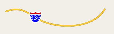
Example 1: interstate highway symbol label

This is a symbol containing an image (could also be paths) and a variable size text string.
<SimpleSymbolDefinition>
  <Name>US_Interstate</Name>
  <Graphics>
    <Image>
      <Reference>Library%3A%2F%2FHighwaySymbols%2FInterstateImage.png</Reference>
      <SizeX>10.8mm</SizeX>
      <SizeY>11.2mm</SizeY>
      <PositionX>0</PositionX>
      <PositionY>0.8</PositionY>
    </Image>
    <Text>
      <String>%INTERSTATE_NUMBER%</String>
      <FontName>Arial</FontName>
      <Height>6mm</Height>
      <PositionX>0</PositionX>
      <PositionY>0</PositionY>
      <HorizontalAlignment>Center</HorizontalAlignment>
      <VerticalAlignment>Middle</VerticalAlignment>
    </Text>
  </Graphics>
  <LineUsage>
    <AngleControl>FromAngle</AngleControl>
    <VertexControl>OverlapNoWrap</VertexControl>
    <Angle>0</Angle>
    <StartOffset>30</StartOffset>
    <EndOffset>30</EndOffset>
    <Repeat>100</Repeat>
  </LineUsage>
</SimpleSymbolDefinition>
The symbol graphics are defined such that the center of the text label is the symbol origin. The image is therefore shifted upwards slightly to compensate for this. The text string is also parametrized. Its value is obtained from an expression in the symbol instance. In this case the expression would be set to the interstate number attribute.
Example 2: line style with simple dashing

The repeating dash pattern is “long dash / dot / short dash / dot”. The long dash is 10 mm long and the short dash is 5 mm long. Each gap is 2.5 mm. The overall period of the dashing is 25 mm. The symbol definition XML would be:
<SimpleSymbolDefinition>
  <Name>LongDash-Dot-ShortDash-Dot</Name>
  <Graphics>
    <Path>
      <Geometry>
        M  0.0,0 L 10.0,0
        M 12.5,0 L 12.5,0
        M 15.0,0 L 20.0,0
        M 22.5,0 L 22.5,0
      </Geometry>
    </Path>
  </Graphics>
  <LineUsage>
    <VertexControl>OverlapWrap</VertexControl>
    <Repeat>25</Repeat>
  </LineUsage>
</SimpleSymbolDefinition>
In the path geometry all the formatting elements (line color, line cap, line join, …) are left out – they take on their default values. For the LineUsage the default vertex control is OverlapNoWrap, and here we set it to OverlapWrap. OverlapWrap means it’s ok to draw the symbol if it overlaps a vertex, but make it bend around the vertex. For simple line styles consisting of centerline dashing, OverlapWrap is the standard behavior we’re used to.
Example 3: line style with a decoration and thickness

The repeating pattern is just a cross. It repeats with period 5 mm.
<SimpleSymbolDefinition>
  <Name>ThickRail</Name>
  <Graphics>
    <Path>
      <Geometry>
        M 0.0, 0.0 L 5.0,0.0
        M 2.5,-2.5 L 2.5,2.5
      </Geometry>
      <LineWeight>%LINE_WEIGHT%=1mm</LineWeight>
      <LineCap>Round</LineCap>
      <LineJoin>Round</LineJoin>
    </Path>
  </Graphics>
  <LineUsage>
    <VertexControl>OverlapWrap</VertexControl>
    <Repeat>5.0</Repeat>
  </LineUsage>
</SimpleSymbolDefinition>
This time the line weight for the path has been parametrized. Its default value is 1 mm and this can be overridden at the symbol instance level. We’ve also changed the path’s line cap and line join styles to round.
Note that when the line weight is modified the spacing between the vertical ticks does *not* change. The path geometry is fixed. If you want the symbol to get bigger / smaller to account for the line weight then this would be done using the symbol instance scales. For example, setting the scales to “1 + LineWeight / 5” would ensure that there is always 5 mm of empty horizontal space between adjacent vertical ticks.
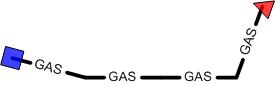
Example 4: line style with start / end symbols

This line style includes text along the centerline, and start / end symbols. In order to store all three components of the line style together we need to make this a compound symbol definition.
<CompoundSymbolDefinition>
  <Name>GasWithStartEndSymbols</Name>
  <Symbols>
    <SimpleSymbolDefinition>
      <Name>GasStyle</Name>
      <Graphics>
        <Path>
          <Geometry>M 0,0 H 5 M 15,0 H 5</Geometry>
          <LineWeight>1mm</LineWeight>
          <LineCap>Round</LineCap>
          <LineJoin>Round</LineJoin>
        </Path>
        <Text>
          <String>GAS</String>
          <FontName>Arial</FontName>
          <Height>3.5mm</Height>
          <PositionX>10</PositionX>
          <PositionY>0</PositionY>
          <HorizontalAlignment>Center</HorizontalAlignment>
          <VerticalAlignment>Middle</VerticalAlignment>
        </Text>
      </Graphics>
      <LineUsage>
        <VertexControl>OverlapWrap</VertexControl>
        <Repeat>20</Repeat>
      </LineUsage>
    </SimpleSymbolDefinition>
    <SimpleSymbolDefinition>
      <Name>BlueSquare</Name>
      <Graphics>
        <Path>
          <Geometry>M -0.5,-0.5 H 1, V 1, H -1, Z</Geometry>
          <FillColor>c00000ff</FillColor>
        </Path>
      </Graphics>
      <LineUsage>
        <VertexControl>OverlapNoWrap</VertexControl>
        <StartOffset>0</StartOffset>
        <Repeat>0</Repeat>
      </LineUsage>
    </SimpleSymbolDefinition>
    <SimpleSymbolDefinition>
      <Name>RedTriangle</Name>
      <Graphics>
        <Path>
          <Geometry>M -0.5,-0.5 H 1, L 0,1, Z</Geometry>
          <FillColor>c0ff0000</FillColor>
        </Path>
      </Graphics>
      <LineUsage>
        <VertexControl>OverlapNoWrap</VertexControl>
        <EndOffset>0</EndOffset>
        <Repeat>0</Repeat>
      </LineUsage>
    </SimpleSymbolDefinition>
  </Symbols>
</CompoundSymbolDefinition>
In this version of the schema the order of the symbols in the compound determines the draw order. Here, the start and end symbols are drawn on top of the dashing. For the start symbol the StartOffset and Repeat are set to 0. This ensures the symbol is only drawn once at the start of the feature. Likewise, for the end symbol we set the EndOffset and Repeat to 0. We also want OverlapNoWrap for the VertexControl. The symbol can overlap a vertex, but we simply want to “stamp” it – no bending around vertices.
One other note: the default AngleControl behavior is FromGeometry. This means the angle of the start / end symbol will be computed from the geometry, as shown here.

If you wanted the start / end symbol angles to be a fixed value you would change AngleControl to FromAngle and specify the Angle, e.g.
    <SimpleSymbolDefinition>
      <Name>BlueSquare</Name>
      ...
      <LineUsage>
        <AngleControl>FromAngle</AngleControl>
        <VertexControl>OverlapNoWrap</VertexControl>
        <Angle>0</Angle>
        <StartOffset>0</Repeat>
        <Repeat>0</Repeat>
      </LineUsage>
    </SimpleSymbolDefinition>

Example 5: line style with a special cross-tick offset requirement

This line style is one that the current MapGuide stylization code can’t handle. The problem is that the cross tick decoration needs to have a different start offset than the other decorations. Our new stylization schema handles this easily though. We have to create a compound symbol definition since we have two symbol components with different distributions.
<CompoundSymbolDefinition>
  <Name>MTYP1500a</Name>
  <Symbols>
    <SimpleSymbolDefinition>
      <Name>UpperLowerDashing</Name>
      <Graphics>
        <Path>
          <Geometry>
            M 0,-2.5 H 8 M 10,-2.5 H 8, M 20,-2.5 H 2
            M 0, 2.5 H 8 M 10, 2.5 H 8, M 20, 2.5 H 2
          </Geometry>
        </Path>
      </Graphics>
      <LineUsage>
        <VertexControl>OverlapWrap</VertexControl>
        <Repeat>24</Repeat>
      </LineUsage>
    </SimpleSymbolDefinition>
    <SimpleSymbolDefinition>
      <Name>OffsetCrossTick</Name>
      <Graphics>
        <Path>
          <Geometry>M 0.0,-2.5 V 5</Geometry>
        </Path>
      </Graphics>
      <LineUsage>
        <VertexControl>OverlapWrap</VertexControl>
        <StartOffset>28</StartOffset>
        <Repeat>24</Repeat>
      </LineUsage>
    </SimpleSymbolDefinition>
  </Symbols>
</CompoundSymbolDefinition>
The upper / lower dashing has zero start offset, whereas the cross tick has a 28 mm offset. This horizontally positions the first cross tick at the center of the first long dash in the second cycle of upper / lower dashing.
Implications
The new symbol definitions and cartographic engine will obviously have an impact on the LayerDefinition XML schema. Those changes will be proposed in a subsequent RFC. That RFC will discuss any potential compatibility issues, however non are anticipated at this time.
Test Plan
Unit tests will be written to verify the new cartographic styling engine. In addition we will also create a sample symbol library to use for testing.
Funding/Resources
Autodesk will provide resources to implement the core symbolization engine and detailed implementation for point symbols and label symbols. If time allows we will also implement some portion of the line symbolization. In the future we plan to finish the symbolization engine to also include area symbolization. Timing for this has yet to be determined.
Appendix A
Attachments (11)
- ex1.jpg (4.1 KB ) - added by 17 years ago.
- ex2.jpg (937 bytes ) - added by 17 years ago.
- ex3.jpg (2.7 KB ) - added by 17 years ago.
- ex4.jpg (2.6 KB ) - added by 17 years ago.
- ex4a.jpg (3.3 KB ) - added by 17 years ago.
- ex4b.jpg (3.2 KB ) - added by 17 years ago.
- ex5.jpg (2.7 KB ) - added by 17 years ago.
- ex6a.jpg (3.7 KB ) - added by 17 years ago.
- ex6b.jpg (3.9 KB ) - added by 17 years ago.
- Symbolization.zip (442.8 KB ) - added by 17 years ago.
-
LineUsage.doc
(567.0 KB
) - added by 13 years ago.
Description of LineUsage behavior
Download all attachments as: .zip